


19
PIPE THE BOILER
A. PREPARATION
1. The boiler must be pressure tested as outlined in
Chapter 3, “Place the Boiler Sections,” of this
manual.
2. The Supply and Return piping can be installed
before the jacket is applied. Use nipples long enough
to be sure they will extend through the jacket.
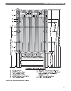
B. SUPPLY PIPING
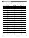
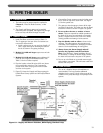
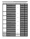
1. Install End Riser connections sized per Table 5.1.
The 3" tappings in the tops of the end sections are
not used for steam boilers.
a. Install a reducing tee on one end riser. Install a 2"
valve, nipple and cap for skimming the boiler in
the tee as shown in the piping drawings.
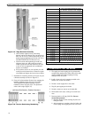
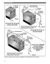
2. Models 211A-08 and larger require risers in both
end sections.
3. Models 211A-18 and larger require additional 3"
risers off of the tapped intermediate sections. See
Table 5.1 for the number required.
4. Pipe the header at least 24 inches (610 mm) above
the normal boiler water line. This is required to
prevent water from carrying over into the header
and then to the system.
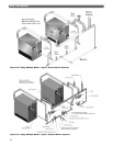
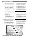
5. Figure 5.2 shows the Supply and Return piping for
Parallel Flow Gravity systems and all Pumped Return
Systems.
6. Counterflow Gravity systems require the boiler steam
line to enter the top of the steam main. See Figure
5.3 for this special case.
7. The piping in these drawings is shown off the right
hand side of the boiler. The boiler may also be piped
toward the left side as shown in Figure 5.4, typical.
8. Do not reduce the size or number of risers
shown. These are required for reliable operation of
the boiler. If the risers are undersized or incorrectly
placed, a sloped water line can occur in the boiler,
causing possible overheating of some sections.
9. Pipe the Header with an offset as shown in the
drawings. This offset prevents the expansion and
contraction of the Header from damaging the boiler
sections. Use threaded fittings for swing joints.
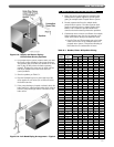
10. Always locate the Steam Supply take-off
between the Equalizer and the last Boiler
Riser. (See PB Heat’s “Steam Installation Survey”
for discussion). Locating the Steam Supply between
the risers will cause water carryover to the system.
11. Do not use a bull head tee to provide steam supply
and equalizer connections. This will cause water level
bounce and carryover.
C. RETURN PIPING
1. The use of a Hartford loop in all installations is
recommended. The loop provides additional
reliability for the system. A check valve must still be
installed on the pump discharge of all pumped return
systems.
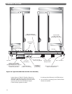
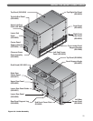
5. PIPE THE BOILER
Figure 5.1: Supply and Return Positions, Skim Piping, Hartford Loop