


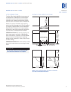
Dimensions in parentheses are in
millimeters unless otherwise specified.10
MODELS 424 AND 424FS INSTALLATION
MODELS
424 | 424FS
PANEL
DESIGN
Additional panel
design information
can be found in
the Sub-Zero
Design Guide.
Check our website
at subzero.com.
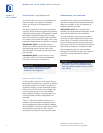
IMPORTANT NOTE:
After the first three or
four mounting screws are in place, but not
c
ompletely tightened, close the door and check
your panel fit. This is the time to make small
adjustments. Once you are satisfied with the
a
ppearance, open the door and apply the
remainder of the screws. Check all screws for
tightness.
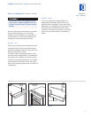
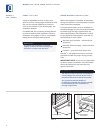
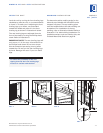
The metal frame on the glass door has
numerous mounting holes on each side of the
door. This is to accommodate the Sub-Zero
accessory handles and provide for easy attach-
ment of the handle through the door frame.
If you choose not to use the pre-drilled handle
mounting holes, it will be necessary to fasten
the handle from the rear of the door panel
only, or drill one or more additional holes
through the metal frame of the glass door.
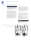
Illustration 10 on page 11 shows how this hole
passes through the door frame. The hole
center is on the small locator groove in the
front of the frame. A
1
/4" (6) diameter hole is
made in the front wall of the extrusion and a
13
/32" (11) diameter hole through the rest of the
frame.
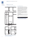
OVERLAY DOOR PANELS
OVERLAY GLASS DOOR – MODEL 424
I
nspect the door panel for the minimum
5
/8"
(16) thickness, the finished inside edge and the
10 lbs (5 kg) weight limit. See the Wine
S
torage section of the Sub-Zero Design Guide
for additional panel information.
Decide if the handle will be attached through
the glass door frame or just through the deco-
rative door panel. If it is just through the door
panel, the handle must be attached first.
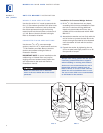
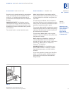
Decorative panels are attached to the Model
424 door using #8 x
5
/8" square drive screws
passing through the door frame from the rear,
behind the gasket into the panel. The door
panel is marked for screw locations by the use
of ‘tenon centers’, which are temporarily
inserted into the
1
/4" (6) diameter holes in the
front of the glass door frame. Refer to illustra-
tion 9 on page 11.
With the Wine Storage unit secured in position
and the door closed, the panel is held in the
desired position on the door and rapped by
hand from the front, putting center marks on
the rear surface of the panel. If the door panel
is made of such a material that pre-drilling is
needed, all of the mounting holes should be
marked. If not, only enough holes to hold the
panel in place temporarily, are necessary.
The door panel is then lowered from the door
frame, tenon centers removed, the door
opened and the screws driven into the panel
through the black tape on the door frame,
using the center marks to locate the screws.
The screw holes inside the door ar
e hidden
under a cover flap on the door gasket. It is
necessary to lift the flap to insert the screws.
Use as many scr
ews as necessar
y to hold the
door panel in place properly.
The wine storage unit door is made with
a sealed double wall tempered glass core.
The drill must not contact this core when
drilling. Be sur
e the hole is centered on
the small groove in the front of the door
frame and the drill passes squarely
through the frame. If you are inexperi-
enced with drilling, fasten the handle from
the r
ear of the door panel only.