


17
Dimensions in parentheses are in
millimeters unless otherwise specified.
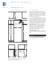
MODELS 427 AND 427R INSTALLATION
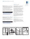
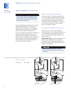
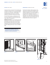
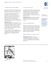
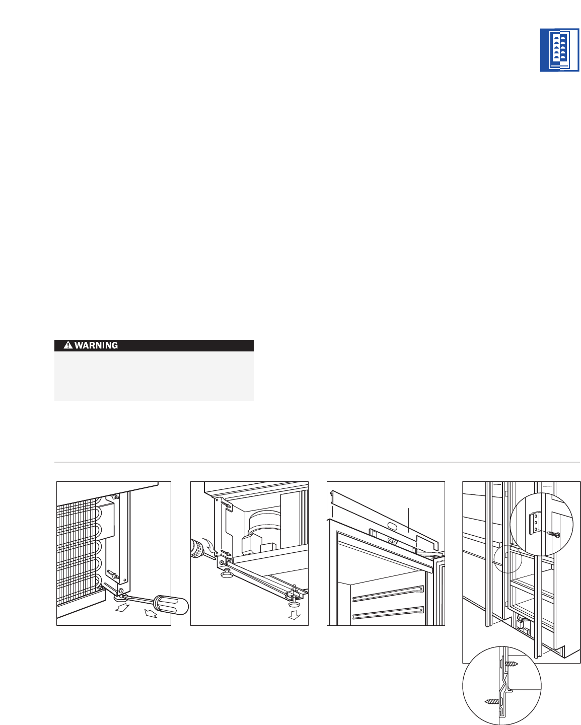
LEVEL THE UNIT
Level the unit by turning the front leveling legs
c
lockwise to raise the unit, or counterclockwise
to lower it. To assist you in adjusting the front
leveling legs up or down, use a standard
screwdriver blade and place it in the front
leveling leg as shown in illustration 4 below.
T
he rear leveling legs are adjusted from the
front of the base by turning the Phillips head
screw. Refer to illustration 5.
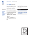
IMPORTANT NOTE:
The rear leveling legs will
only move
1
/16" (2) for every 18 revolutions on
the Phillips head screw. Do not over torque.
Use the lowest torque setting on any power
screwdriver. Do not turn the rear leveling legs
by hand. Damage will occur if you turn these
legs.
To reduce the possibility of the unit
tipping forward, the front leveling legs
must be in contact with the floor.
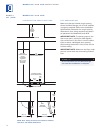
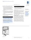
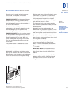
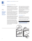
MOLDING INSTALLATION
The decorative white molding strips for the
s
ide and top of Models 427 and 427R can be
snapped into place. The top molding piece
must be installed before the side molding can
be attached. For installation of the top
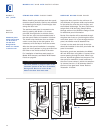
molding, refer to illustration 6 below. Refer to
illustration 7 for side molding installation. For
installations where units are side by side, see
Finished Wood Side Panels on page 23.
Top Molding
Illus. 4
Illus. 5
Illus. 6
Illus. 7
MODELS
427 | 427R