


9
Dimensions in parentheses are in
millimeters unless otherwise specified.
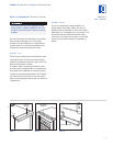
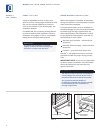
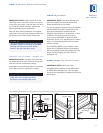
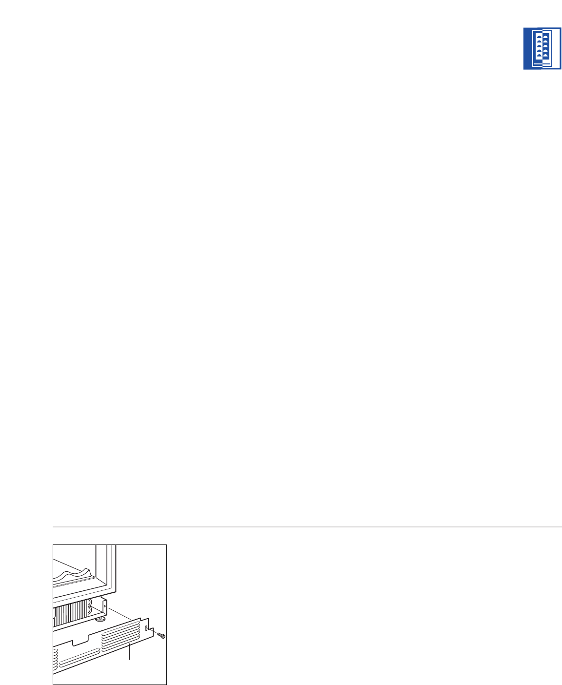
KICKPLATE INSTALLATION
Once the unit is leveled and wiring connections
m
ade, the kickplate can be installed. Use the
two #10 x
1
/2" stainless steel screws that are
provided with the kickplate. Refer to illustration
8 below.
IMPORTANT NOTE:
The kickplate must be
r
emoved for servicing. The floor cannot inter-
fere with removal. The louvered section of the
kickplate must not be covered so as to prevent
air circulation.
Turn power back on to the electrical outlet.
MODELS 424 AND 424FS INSTALLATION
Kickplate
Illus. 8
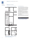
DOOR PANELS – MODEL 424
Model 424 is offered in two design applica-
tions; stainless steel (/S) and overlay (/O). Each
o
f these designs are available as a glass door
(G) model.
The stainless steel Model 424 is available in
the classic finish only and is shipped from the
f
actory with the decorative stainless steel door
panel and matching handle in place.
The overlay Model 424/O is designed to accept
a decorative door panel to match surrounding
cabinetry. The door panel and the handle will
be provided by the customer.
The solid door Model 424S—with no glass
window—requires a different door panel than
the glass door design.
Before beginning installation, check for the
correct components for the fit and finish
desired. All overlay doors require a decorative
panel 23
3
/4" (603) by 30
1
/16" (764) and a
minimum
5
/8" (16) thick.
IMPORTANT NOTE:
For installations at or
above 5,000' (1524 m) in altitude, a special
high altitude glass door unit (HA) must be
ordered.
If you have questions, contact your Sub-Zero
dealer or cabinet supplier. Additional panel
information can be found in the Sub-Zero
Design Guide.
PANEL
DESIGN
Additional panel
design information
can be found in
the Sub-Zero
Design Guide.
Check our website
at subzero.com.
MODELS
424 | 424FS