


8
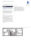
LEVEL THE UNIT
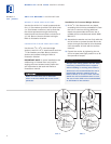
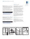
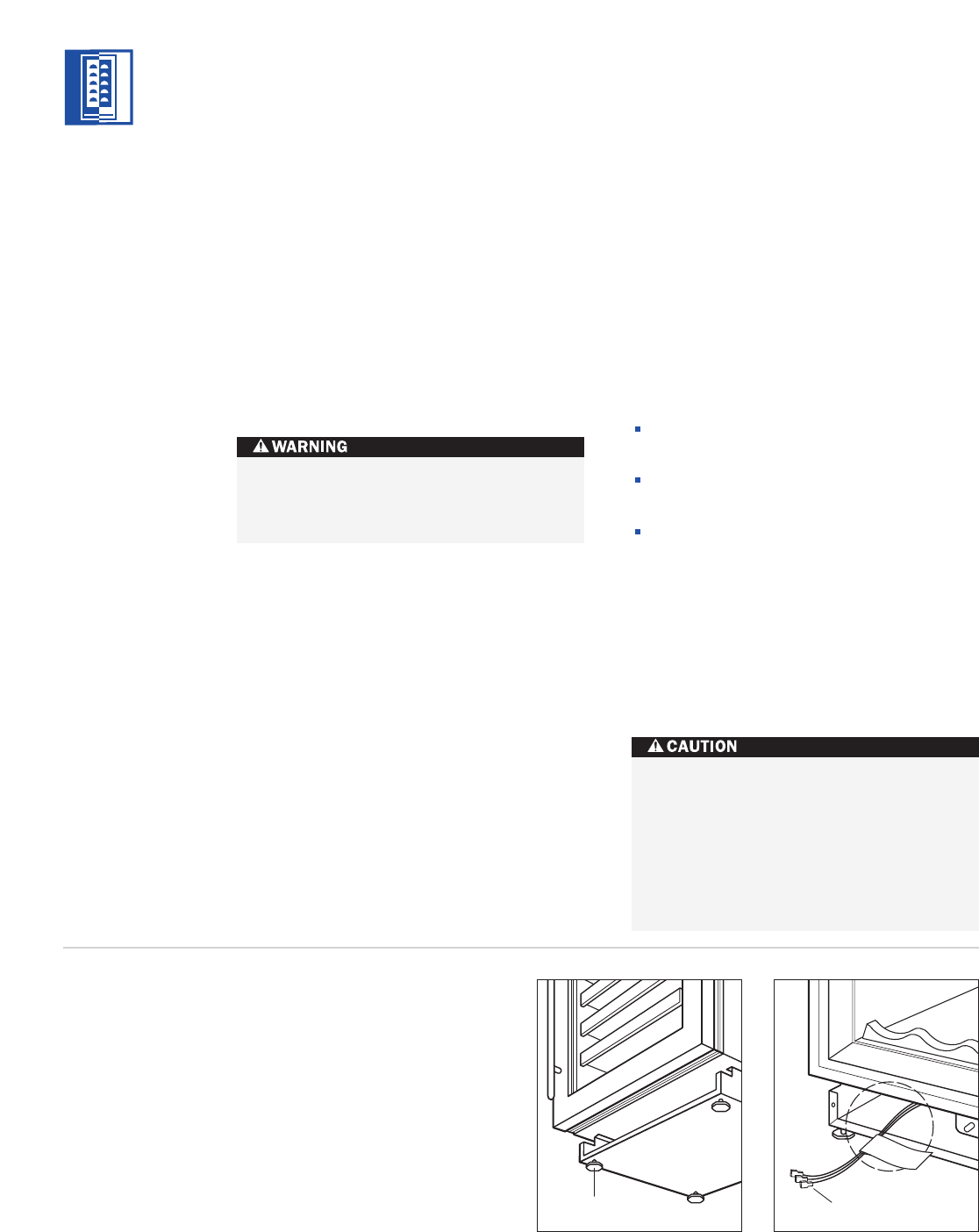
Using an adjustable wrench or pliers, turn
e
ach of the four leveling legs clockwise to raise
the unit and counterclockwise to lower the
unit. For the location of the leveling legs, see
illustration 6 below.
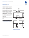
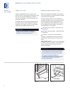
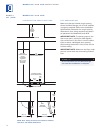
For Model 424, the countertop bracket should
b
e used to make a solid installation. Refer to
illustration 2 on page 5. If this is not possible,
wedge shims along the sides and top.
MODELS 424 AND 424FS INSTALLATION
Leveling Legs
Home Alarm
Connections
Illus. 6
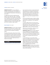
Illus. 7
HOME ALARM CONNECTIONS
Before the kickplate is installed, all necessary
wiring connections in the compressor compart-
m
ent should be completed.
I
f a home alarm system is to be installed on
the Wine Storage unit, the connections should
be made using the logic supplied with the
a
larm specifications. See illustration 7 below
for the appliance lead locations, and refer to
the following for color codes:
Normally open contacts – white with red
stripe wire
Normally closed contacts – white with blue
stripe wire
Common – gray with white stripe wire
Use the
1
/4" (6) spade terminals or wire nuts
provided to make the proper wiring connec-
tions.
IMPORTANT NOTE:
If you are not responsible
for alarm system connection, this information
should be supplied to the home security
system contractor.
To reduce the possibility of the unit
tipping forward, the front leveling legs
must be in contact with the floor.
The alarm circuit in the unit is intended as
a low-voltage, low-current device only. It
should not be used to switch line power.
Any unused terminals should be
completely insulated and all wires should
be secur
ed away from conductive or
moving components.
MODELS
424 | 424FS