


27
MODEL 430 INSTALLATION INSTRUCTIONS
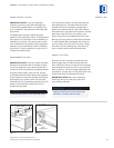
If a home alarm system is to be used with the
W
ine Storage unit, the lead wires should be
threaded into the compressor compartment
before you position the unit. See Home Alarm
Connections on page 28 for the location of these
lead wires. After the unit is in position, the
alarm wiring can be completed from the front.
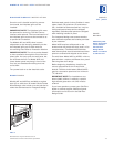
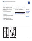
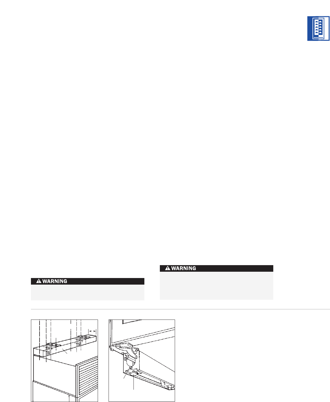
Roll the unit into position under the wood block
or soffit. Model 430 is equipped with rollers so
you can easily move the unit into place. Using
the front and rear leveling legs, raise the unit
until it makes contact with the wood block.
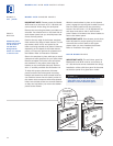
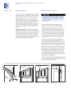
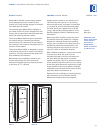
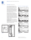
LEVEL THE UNIT
Once the unit is in position, extend the front
leveling legs down to make contact with the
floor. Level the unit by turning the front leveling
legs clockwise to raise the unit, or counterclock-
wise to lower it. The rear height adjustment can
be made by turning the
5
/16" hex bolt at the front
of the base. Refer to illustration 6 below.
IMPORTANT NOTE:
Be sure to reference
leveling of the unit to the floor and not to
surrounding cabinetry.
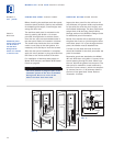
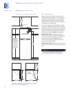
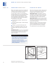
3"
(76)
WOOD BLOCK
SHROUD
WALL STUD
SCREW
Illus. 5
Illus. 6
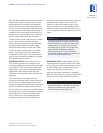
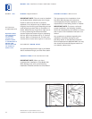
LOCK INSTALLATION
IMPORTANT NOTE:
If you are adding an
a
ccessory lock kit to your Wine Storage unit,
it should be installed before you position the
unit. Installation instructions are included with
the lock kit.
For Model 430, the lock is attached to the
b
ottom of the metal door frame. The decorative
door panel is not involved in the installation or
operation of the lock. The catch portion of the
lock is attached to the bottom of the appliance
cabinet in pre-punched holes. When installing
the lock kit, it may be helpful to tip the unit on
its back for easier access.
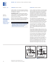
POSITION THE UNIT
IMPORTANT NOTE:
If for any reason the Wine
Storage unit has been laid on its back or side,
you must allow the unit to stand upright for a
minimum of 24 hours before connecting power.
Plug the power supply cord into the 15 amp
grounded electrical outlet. With power applied
to the appliance, check for lighting and cooling
before going any further. Once you are satis-
fied that the unit is operating properly, shut off
power to the electrical outlet at the circuit
breaker and proceed.
Shut of
f the power to the electrical outlet.
Rear
Adjustment
F
ront
Le
veling Leg
To reduce the possibility of the unit
tipping forward, the front leveling legs
must be in contact with the floor.
MODEL 430
Dimensions in parentheses are in
millimeters unless otherwise specified.