


25
Dimensions in parentheses are in
millimeters unless otherwise specified.
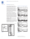
UNPACKING AND MOVING
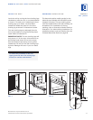
Uncrate the unit, remove its wood base and
discard the shipping bolts that hold the wood
b
ase to the bottom of the unit. Remove all
packing materials and tape.
IMPORTANT NOTE:
Do not discard the
kickplate, anti-tip blocking kit and hardware.
T
hese items will be needed for the installation.
All roller-assembly wine shelves should be
removed to reduce weight and prevent them
from rolling. To remove, pull the shelf out to
its full extension, gently and evenly lift up on
both sides of the front of the shelf and remove.
Reverse the procedure to reinstall the shelf.
Retract the front leveling legs to allow you to
move the unit more easily during installation.
You will extend the leveling legs when the unit
is in its final position to reduce the possibility
of the unit tipping forward.
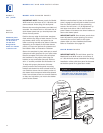
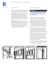
Use an appliance dolly to move the unit.
Remove the drain pan from the base of the
unit to avoid damage to the drain pan, and
allow for proper placement of the appliance
dolly.
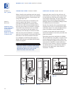
ELECTRICAL REQUIREMENTS
A 115 V AC, 60 Hz, 15 amp circuit breaker and
e
lectrical supply are required. A separate
circuit, servicing only this appliance, is
required.
The power supply cord has a 3-prong ground-
ing plug, which must be plugged into a mating
3
-prong grounding-type wall receptacle. Follow
the National Electrical Code and local codes
and ordinances when installing the receptacle.
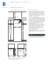
For location of the electrical supply, refer to the
Installation Specifications illustration.
IMPORTANT NOTE:
A ground fault circuit
interrupter (GFCI) is not recommended and
may cause interruption of operation.
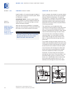
HOME ALARM SYSTEM
If a home alarm system is to be used, refer to
Home Alarm Connections on page 28. In
addition to operating power, the installer may
also be required to supply a home automation
system lead to the unit. This is for a low-
voltage, low-curr
ent signal similar to door and
window sensor signals. Common, nor
mally
open and normally closed contact configura-
tions are provided.
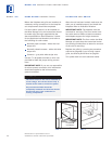
Three
1
/4" (6) female spade connectors are
located in the compressor compartment and
are accessible behind the grille on Model 430.
A minimum of 36" (914) of lead wire should be
provided for each contact, exiting the back wall
near the electrical outlet.
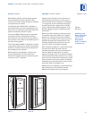
MODEL 430 INSTALLATION INSTRUCTIONS
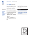
Before moving the Wine Storage unit in
to position, protect any finished flooring
with appropriate materials, secure the
door closed and remove the grille.
Do not use an extension cord or two-
prong adapter. Electrical ground is
required on this appliance.
MODEL 430