


English 9
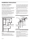
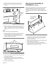
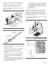
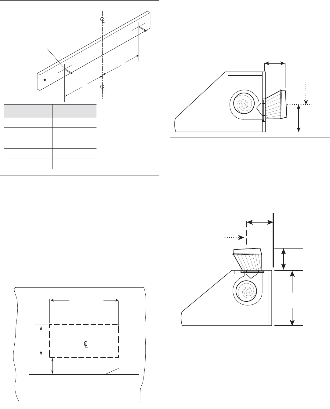
8. On the wood bracket, mark the locations used to hang
the hood according to Figure 8.
9. Drill a 3/16” (4.8 mm) tap hole through the wooden
bracket and wall. These 5/8” (16 mm) screws do not
need to go into the studs.
10. Use (2) 5/8” (16 mm) screws to secure the wood
bracket leaving ¼” (6 mm) of each screw exposed for
hanging the hood.
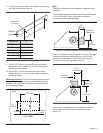
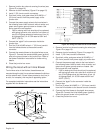
Discharge Direction: Horizontal discharge requires a wall
cutout, as shown in Figure 9, to provide clearance for the
transition. The location of the cutout is determined by the
hood installation height.
Note:
Dashed line indicates cutout needed for clearance of the
transition.
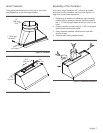
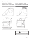
The transition supplied with the hood connects to standard
10-inch round duct. Figure 10 shows the transition
connected for horizontal discharge.
Figure 11 shows the hood configured for vertical discharge.
Installations using this method require a cutout in the
ceiling to accommodate 10" (254 mm) duct and the ½”
(13 mm) conduit carrying power to the unit.
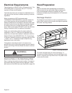
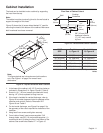
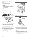
Duct covers, sold separately, are available to cover the
space between the top of the hood and ceiling (see
Figure 14).
Figure 8: Hanging the Hood
Figure 9: Cutout Dimensions
Wooden
Bracket
Screws 2 ea
3” (76 mm)
A
A
HOOD SIZE A
30” (762 mm) 13” (330 mm)
36” (914 mm) 16” (406 mm)
42” (1067 mm) 19” (483 mm)
48” (1219 mm) 22” (559 mm)
54” (1372 mm) 25” (635 mm)
Dry Wall
12½”
(318 mm)
23” (584 mm)
2¾” (69 mm)
Base of Hood
Location
Cooktop Centerline
Figure 10: Transition Centerline for Horizontal Discharge
Figure 11: Transition Centerline for Vertical Discharge
10¼”
(260 mm)
10½”
(267 m
m)
Transition
Centerline
10¼”
(260 mm)
18”
(457 mm)
Transition
Centerline
W
A
L
L
5
13
/
16
”
(148 mm)