


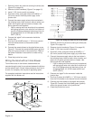

English 14
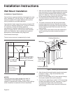
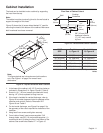
1. Remove junction box channel covering the wires (see
Figure 12 on page 10).
2. Remove circular knockouts (Figure 12 on page 10).
3. Install 1” (25.4 mm) conduit connectors.
4. Run black, white, and green wires (#12 AWG) in 1”
(25.4 mm) conduit from the power supply to the
junction box.
5. Connect the power supply wires to the hood wires in
the following order: black to black, white to white, and
green wire to green ground screw on chassis. Use
spring type wire nuts supplied.
• Lost or missing wire nuts should only be replaced
with spring type wire nuts, rated for a minimum of
two (2) #18 gauge wires and maximum of four (4)
#14 gauge wires, UL & CSA rated to 600V and
302°F (150°C).
6. Connect the “pigtail” to the connector inside the
junction box.
7. Run five (5) #14 AWG wires in 1” (25.4 mm) conduit
from the remote blower to the second conduit
connector.
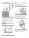
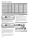
8. Connect the remote blower to the pigtail wires as per
Figure 21. Connect the remote blower green (ground)
wire to the ground screw in the junction box. Refer to
the blower installation instructions for further wiring
details.
9. Close the junction box cover.
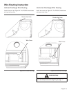
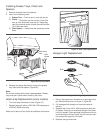
Wiring the Hood with an Inline Blower
To minimize noise in the kitchen, these blowers are
mounted along the duct line anywhere between the kitchen
and the exterior wall. If there is easy access to duct line (in
an attic, for example), this may be an appealing option.
For complete installation instructions see the instructions
supplied with the blower unit.
1. Remove junction box channel covering the wires (see
Figure 12 on page 10).
2. Remove circular knockouts (Figure 12 on page 10).
3. Install 1” (25.4 mm) conduit connectors.
4. Run black, white, and green wires (#12 AWG) in 1”
(25.4 mm) conduit from power supply to junction box.
5. Connect the power supply wires to the hood wires in
the following order: black to black, white to white, and
green wire to green ground screw on chassis. Use
spring type wire nuts supplied.
• Lost or missing wire nuts should only be replaced
with spring type wire nuts, rated for a minimum of
two (2 #18 gauge wires and maximum of four (4)
#14 gauge wires, UL & CSA rated to 600V and
302°F (150°C).
6. Connect the “pigtail” to the connector inside the
junction box.
7. Run five (5) wires (#14 AWG) in 1” (25.4 mm) conduit
from the inline blower to the second conduit connector.
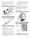
8. Connect the inline blower to the pigtail wires as per
Figure 23. Connect the inline blower green (ground)
wire to the ground screw in the junction box.
9. Close the junction box cover.
Figure 22: VTI1010D Inline Blower
12
1/
8
"
(308 mm)
14
3/
8
"
(365 mm)
7/
8
" (22 mm)
1
3/
4
"
(44 mm)
19
1/
8
"
(486 mm)
ø9
7/
8
"
(251 mm)
12
"
(305 mm)
12
7/
8
"
(327 mm)
Figure 23: Wiring the Hood with an Inline Blower