


21
CVHE-SVU01E-EN
General
Information
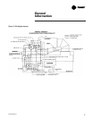
Free Cooling Cycle
Based on the principle that refrigerant
migrates to the coldest area in the
system, the free cooling option
adapts the basic chiller to function as
a simple heat exchanger. However, it
does not provide control of the
leaving chilled water temperature.
If condenser water is available at a
temperature lower than the required
leaving chilled water temperature, the
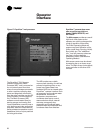
operator interface must remain in
“AUTO” and the operator starts the
free cooling cycle by enabling the
Free cooling mode in the
“DynaView
™
Feature Settings” group
of the operator interface, or by means
of a Tracer request.
Several components must be factory-
installed or field-installed to equip the
unit for free cooling operation:
— a refrigerant gas line, and
electrically-actuated shutoff valve,
between the evaporator and
condenser;
— a valve liquid return line, and
electrically-actuated shutoff valve,
between the condenser sump and
the evaporator;
— a liquid refrigerant storage vessel
(larger economizer); and,
— additional refrigerant.
When the chiller is changed over to
the free cooling mode, the
compressor will shut down if
running, the shutoff valves in the
liquid and gas lines open; unit
control logic prevents the
compressor from energizing during
free cooling. Liquid refrigerant then
drains (by gravity) from the storage
tank into the evaporator and floods
the tube bundle. Since the
temperature and pressure of the
refrigerant in the evaporator are
higher than in the condenser (i.e.,
because of the difference in water
temperature), the refrigerant in the
evaporator vaporizes and travels to
the condenser. Cooling tower water
causes the refrigerant to condense,
and it flows (again, by gravity) back
to the evaporator.
This compulsory refrigerant cycle is
sustained as long as a temperature
differential exists between condenser
and evaporator water. The actual
cooling capacity provided by the free
cooling cycle is determined by the
difference between these
temperatures which, in turn,
determines the rate of refrigerant flow
between the evaporator and
condenser shells.
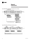
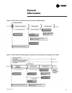
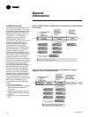
If the system load exceeds the
available free cooling capacity, the
operator must manually initiate
changeover to the mechanical
cooling mode by disabling the free
cooling mode of operation. The gas
and liquid line valves then close and
compressor operation begins. (See
Figure 8 beginning at “Auto” mode.)
Refrigerant gas is drawn out of the
evaporator by the compressor, where