


93
CVHE-SVU01E-EN
Maintenance
Other Maintenance
Requirements
Compressors using new seal
technology will not use O-rings. The
O-ring has been replaced by Loctite
515 applied at a minimum film
thickness of .010 applied across the
width of the flange. The current jack
bolt holes remain for disassembly.
CAUTION
Oil Supply System
Problems!
Plugging of oil supply system could
lead to bearing failure. Failure to use
care could result in Loctite getting
into the chiller which may cause
problems with the Oil supply
system and eductor system.
[ ] Inspect the condenser tubes for
fouling; clean if necessary.
ƽƽ
ƽƽ
ƽ WARNING
Hazardous Voltage w/
Capacitors!
Disconnect all electric power,
including remote disconnects before
servicing. Follow proper lockout/
tagout procedures to ensure the
power cannot be inadvertently
energized. For variable frequency
drives or other energy storing
components provided by Trane or
others, refer to the appropriate
manufacturer’s literature for
allowable waiting periods for
discharge of capacitors. Verify with
an appropriate voltmeter that all
capacitors have discharged. Failure
to disconnect power and discharge
capacitors before servicing could
result in death or serious injury.
Note: For additional information
regarding the safe discharge of
capacitors, see PROD-SVB06A-EN or
PROD-SVB06A-FR
[ ] Measure the compressor motor
winding resistance to ground; a
qualified service technician should
conduct this check to ensure that the
findings are properly interpreted.
Contact a qualified service
organization to leak-test the chiller;
this procedure is especially
important if the system requires
frequent purging.
[ ] Use a nondestructive tube test to
inspect the condenser and evaporator
tubes at 3-year intervals.
Note: It may be desirable to perform
tube tests on these components at
more frequent intervals, depending
upon chiller application. This is
especially true of critical process
equipment.
[ ] Depending on chiller duty, contact
a qualified service organization to
determine when to conduct a
complete examination of the unit to
discern the condition of the
compressor and internal
components.
Note: (a) Chronic air leaks, which can
cause acidic conditions in the
compressor oil and result in
premature bearing wear; and, (b)
Evaporator or condenser water tube
leaks. Water mixed with the
compressor oil can result in bearing
pitting, corrosion, or excessive wear.
[ ] Submit a sample of the
compressor oil to a Trane qualified
laboratory for comprehensive
analysis on an annual basis; this
analysis determines system moisture
content, acid level and wear metal
content of the oil, and can be used as
a diagnostic tool.
Lubrication
The only CVHE, CVHF and CVHG
chiller component that requires
periodic lubrication is the external
vane linkage assembly and Rotary oil
valve.
Lubricate the vane linkage shaft
bearings and rod end bearings as
needed with a few drops of light-
weight machine oil.
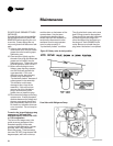
The CenTraVac inlet guide vane tang
operators should be serviced
annually with R123 compatible
grease. Use only Rheolube 734A,
available from Trane as LUB00033
(16oz. standard grease gun cartridge)
or LUB00063 (3oz. mini grease gun
cartridge)
To service the 1st stage tang
operator of all units except CVHF
extended capacity chillers with 1470
or 1720 compressors.
1. The chiller must be off.
2. Carefully remove any insulation
that may have been placed over the
two lubrication ports of the tang
operator base. This insulation will
need to be replaced after the
service is complete.
3. Note the position of the tang
operator arm, note the placement
of spacing washers etc., then
disconnect the linkage rod from
the tang operator arm. Manually
move the tang operator arm and
note the amount of effort required
to operate the assembly.
4. Loosen but DO NOT REMOVE the
1/16" NPT lubrication port plug that
is highest on the assembly.
5. Loosen and remove the remaining
lower 1/16" NPT plug.
6. Using a grease gun with an
appropriate fitting, insert ONLY
Rheolube grease into the open port
until clean grease is seen to appear
around the threads of the plug in
the opposite port.
7. Tighten the plug that was loosened
in step 4. Tighten the plug to hand
tight plus 1/4 to 1/2 turn.
8. Remove the grease fitting, if used.