


53
CVHE-SVU01E-EN
Head Relief Request Output
When the chiller is running in
Condenser Limit Mode or in Surge
Mode, the head relief request relay
(1 minute default) on the 1A9–J2-6 to
J2-4 will be energized and can be
used to control or signal for a
reduction in the entering condenser
water temperature. Designed to
prevent high refrigerant pressure trip-
outs during critical periods of chiller
operation.
If the unit is not equipped with the
CDPR Enhanced Condenser Limit
Option the unit will use the
condenser refrigerant temperature
sensor (input converted to saturated
refrigerant pressure) to perform the
Standard Condenser Limit function,
without the head relief request relay,
by limiting inlet guide vane stroke
and chiller capacity.
Keep in mind that Condenser Limit
Control supplements the protection
provided by the condenser pressure
high pressure cutout switch 3S1.
Compressor Motor Winding
Temp Sensor Module
The motor temperature module 1A26
connects via unit wiring to the three
motor winding temperature sensors.
Maximum Capacity Relay
(TechView adjustable)
When the chiller has been operating
at maximum capacity for 10 minutes
(TechView adjustable 1 to 60 min.)
this relay will activate. Also upon
being less than maximum capacity
for 10 minutes this relay will
deactivate.
Compressor Running Relay
Relay activates while compressor is
running.
Machine Shutdown Manual
Reset (MMR)
Limit warning machine shutdown
auto reset relays will activate with
such conditions for remote status
indication.
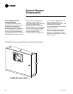
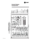
Control System
Components
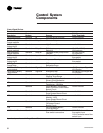
OPST Operation Status Option
Relay output modules 1A8 and 1A9 provide relay outs as shown:
1A8 Optional Quad Relay OPST Relay #1 Compressor running relay, J2-10 NO, J2-11 NC,
Output Status J2-12 common
1A8 Optional Quad Relay OPST Relay #2 MMR Alarm Relay, J2-7 NO, J2-8 NC,
Output Status (Latching) J2-9 common
1A8 Optional Quad Relay OPST Relay #3 Limit Warning Relay, J2-4 NO, J2-5 NC,
Output Status J2-6 common
1A8 Optional Quad Relay OPST Relay #4 MAR Alarm Relay J2-1 NO, J2-2 NC,
Output Status (Non-Latching) J2-3 common
1A9 Optional Quad Relay OPST Relay #2 Purge Alarm Relay J2-7 NO, J2-8 NC,
Output Status J2-9 common
1A9 Optional Quad Relay OPST Relay #3 Head Relief Request Relay J2-4 NO, J2-5 NC
Output Status to J2-6 common
1A9 Optional Quad Relay OPST Relay #4 Maximum Capacity Relay J2-1 NO, J2-2 NC,
Output Status to J2-3 common
Chilled and Condenser Water
Flow Interlock Circuits
Proof of chilled water flow for the
evaporator is made by the closure of
flow switch 5S1 and the closure of
auxiliary contacts 5K1 on terminals
1X1-5 and 1A6-J3-2. Proof of
condenser water flow for the
condenser is made by the closure of
flow switch 5S2 and the closure of
auxiliary contacts 5K2 on terminals
1X1-6 and 1A6-J2-2.