


15
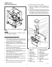
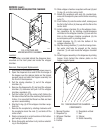
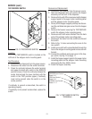
FROTHER AND MIXING/WHIPPER CHAMBER
FIG. 6 FROTHER AND
MIXING/WHIPPER CHAMBER
P1923
Location:
The frother is located behind the dispenser door,
mounted on the front panel and inside the whipper
chamber.
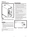
Removal, Cleaning and Replacement:
1. Disconnect the dispenser from the power source.
2. Open the dispenser door and lift the front edge of
the hopper over the retainer plates on the hopper
support panel and slide the hopper assembly out
the front of the dispenser.
3. Pull the mixing chamber (1) out of the whipper
chamber (3).
4. Remove the dispense tip (2) and twist the whipper
chamber (3) clockwise and pull it off the whipper
chamber receptacle (6).
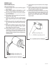
5. Pull the frother (5) off the motor shaft. Notice the
flat side on the shaft and the matching flat inside the
frother. It is important that these two flats are lined
up when reassembling.
6. Slip the O-ring (4) off the whipper chamber recep-
tacle (6).
7. Remove the receptacle by rotating clockwise until
the receptacle clears the nuts (7) and slide off the
motor shaft.
8. Wash components in a mild solution of dish deter-
gent using a bristle brush.
9. Rinse thoroughly and allow to dry before reinstall-
ing in the dispenser.
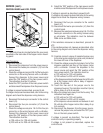
10. Slide whipper chamber receptacle with seal (6) and
O-ring (4) on to the motor shaft.
11. Rotate the receptacle with seal (6) counterclock-
wise until it snaps into place on the motor mounting
nuts (7).
12. Push frother (5) onto the motor shaft, making sure
the flat in the frother (5) lines up with the flat on the
motor shaft.
13. Install whipper chamber (3) on the whipper cham-
ber receptacle (6) by twisting counterclockwise
until tabs on the whipper chamber (3) lock with the
tabs on the whipper chamber receptacle (6). Be
sure dispense port is pointing down.
14. Install dispense tip (2) into the bottom of the
whipper chamber (3).
15. Slip the mixing chamber (1) onto the mixing cham-
ber water inlet tube far enough so the mixing
chamber (1) will seat inside the whipper chamber
(3).
16. Install hopper assembly in the dispenser by sliding
hopper firmly behind the retainer plates on the
hopper support panel.
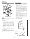
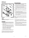
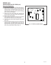
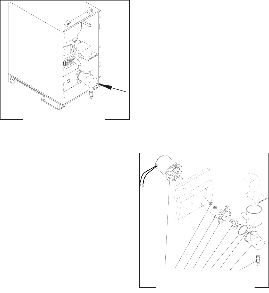
FIG. 7 MIXING/WHIPPER CHAMBER
COMPONENTS
1. Mixing Chamber
2. Dispense Tip
3. Whipper Chamber
4. O-Ring
5. Frother
P1895
6. Receptacle w/Seal
7. Nut
8. Slinger
9. Motor Assembly
SERVICE (cont.)
9 8 7 6 5 4 1 3 2
29793 061599