


21
SERVICE (cont.)
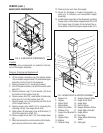
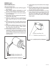
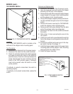
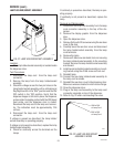
TEST/SERVICE SWITCH
FIG. 13 TEST/SERVICE SWITCH
P1923
Location:
The TEST/SERVICE switch is located on the
left front of the whipper motor mounting panel.
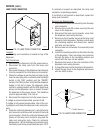
Test Procedure:
1. Disconnect the dispenser from the power source.
2. Disconnect the wires from the switch terminals.
3. Check for continuity between the center terminal
and upper terminal with switch in the SERVICE
position (lower). Check for continuity between the
center terminal and the lower terminal with the
switch in the TEST position (upper). Continuity
must not be present when the switch is in the
center position.
If continuity is present as described, the switch is
operating properly.
If continuity is not present as described, replace the
switch.
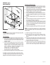
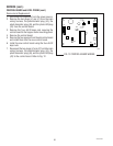
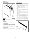
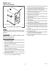
WHI/ORN from Control
Board J1-6
GRN from Control
Board J1-8
BLU/BLK from Control
Board J1-11
FIG. 14 TEST/SERVICE SWITCH
TERMINALS
P1906
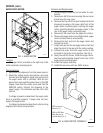
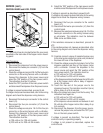
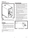
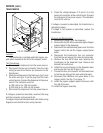
Removal and Replacement:
1. Disconnect the dispenser from the power source.
2. Open the dispenser door and remove the hopper
assembly out the front of the dispenser.
3. Remove the four #8-32 screws securing the hopper
support panel to the auger motor mounting panel
and the whipper motor mounting panel.
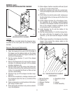
4. Slowly lift the hopper support panel up and discon-
nect the red/black and green wires from the hopper
switch.
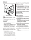
5. Remove the facenut securing the TEST/SERVICE
switch the whipper motor mounting panel.
6. Remove switch with wires attached from the back
side of the whipper motor mounting panel.
7. Disconnect the wires from the switch and discard
the switch.
8. Refer to Fig. 14 when connecting the wires to the
new switch.
9. Install new switch with wires attached through the
hole in the whipper mounting panel and secure with
facenut.
10. Connect the red/black and green wires to the hop-
per switch. See Fig. 10 on page 17.
11. Install the hopper support panel to the auger motor
mounting panel and the whipper motor mounting
panel using the four #8-32 screws.
12. Install the hopper assembly.
29793 061599