


29
SERVICE (cont.)
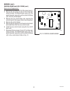
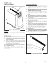
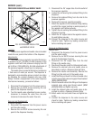
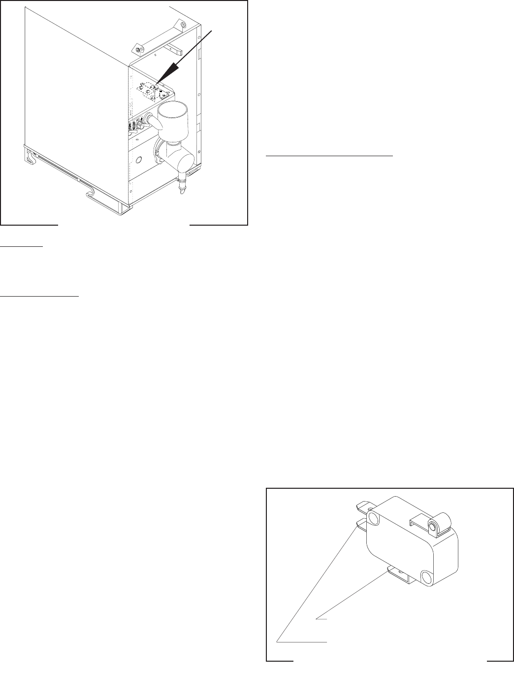
HOPPER SWITCH
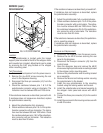
FIG. 26 HOPPER SWITCH
P1933
Location:
The hopper switch is located under the hopper
support panel.
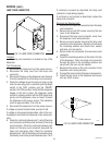
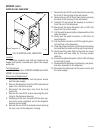
Test Procedures:
1. Disconnect the dispenser from the power source.
2. Open the dispenser door and remove the hopper.
3. Manually engage and release the hopper switch
actuator. The actuator must operate smoothly with-
out binding at either end of its travel and an audible
click must be detected near the mid point of travel.
If the actuator operates as described, proceed to #4.
If the actuator does not operate as described, loosen
the hopper switch mounting screws, realign the switch,
and repeat the process. If the audible click cannot be
detected, proceed to #4.
4. Disconnect the twelve pin connector (J1) from the
control board.
5. Check continuity between pins 8 & 10 on the
harness using an ohmmeter. Continuity must be
present when the hopper is correctly installed.
Continuity must not be present when the hopper is
removed.
6. Reconnect the twelve pin connector (J1) to the
control board.
If continuity is present as described, the hopper switch
is operating properly.
If continuity is not present as described, proceed to #7.
7. Disconnect the wires from the hopper switch.
8. Check continuity between the N.O. and COM. termi-
nals of the hopper switch using an ohmmeter.
Continuity must be present when the actuator is
engaged. Continuity must not be present when
actuator is released.
If continuity is present as described, refer to wiring
diagram and check the dispenser wiring harness.
If continuity is not present as described, replace the
hopper switch.
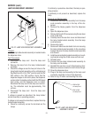
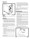
Removal and Replacement:
1. Disconnect the dispenser from the power source.
2. Open the dispenser door and remove the hopper.
3. Remove the four #8-32 screws securing the hopper
support panel.
4. Carefully lift the hopper support panel, remove the
wires from the hopper switch, and remove the
hopper support panel.
5. Noting the orientation of the switch, remove the two
#4-40 screws, lockwashers and nuts securing the
switch to the panel.
6. Attach the new switch to the panel taking care to
orient it properly and secure with two #4-40 screws,
lockwashers and nuts.
7. Manually engage and release the hopper switch
actuator. The actuator must operate smoothly with-
out binding at either end of its travel. If the actuator
operates as described, proceed to #8. If the actua-
tor does not operate as described, loosen the two
screws and realign the switch and repeat the pro-
cess.
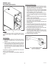
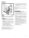
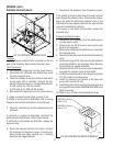
8. Refer to Fig. 27 and reconnect the wires.
9. Install the hopper support panel and secure with
four #8-32 screws.
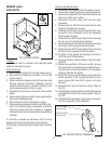
FIG. 27 HOPPER SWITCH TERMINALS
P1904
GRN to Control Boad (J1-8)
RED/BLK to Control Board (J1-10)
29793 061599