


31
SERVICE (cont.)
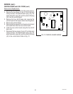
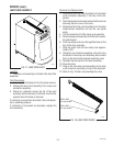
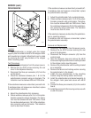
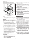
PRESSURE REGULATOR and NEEDLE VALVE
FIG. 30 PRESSURE REGULATOR
and NEEDLE VALVE
P1935
Location:
The pressure regulator and needle valve are located
inside the rear panel at the bottom of the dispenser.
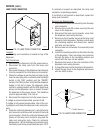
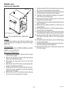
Adjustments:
The water pressure regulator is preset at the factory
to produce 15 psi (103 kPa) of water pressure at the
regulator outlet with inlet pressures ranging from 20
psi to 90 psi (138 to 620 kPa). No field adjustments of
the pressure regulator should ever be necessary.
The needle valve is preset at the factory to dispense
1 fluid ounce of water per second. The dispenser is
designed to accommodate various product mix ratios
by adjusting the product dispense rate (see Initial
Setup). Should a readjustment of the water dispense
rate become necessary, proceed as follows:
1. Disconnect the dispenser from the power source.
2. Remove the six #8-32 screws securing the rear
panel to the dispenser housing.
3. Turn the needle valve adjustment screw counter-
clockwise to increase the water flow rate, and
clockwise to decrease the water flow rate.
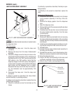
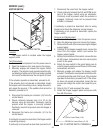
Removal and Replacement:
Pressure Regulator
1. Disconnect the dispenser from the power source
and the water supply.
2. Remove the six #8-32 screws securing the rear
panel to the dispenser housing.
3. Disconnect the .25" copper tube from the outlet of
the pressure regulator.
4. Loosen the nut securing the bulkhead fitting to the
dispenser.
5. Remove the bulkhead fitting from the inlet to the
pressure regulator.
6. Remove the pressure regulator assembly.
7. Attach the regulator to the bulkhead fitting making
sure that the copper bushing is seated properly in
the regulator and tighten securely.
8. Tighten the nut securing the bulkhead fitting to the
dispenser housing.
9. Attach the .25" copper tube to the regulator assem-
bly and tighten securely.
10. Connect the dispenser to the water source and
check for leaks. Tighten any leaking connections
before installing rear panel.
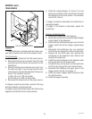
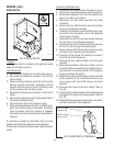
Removal and Replacement:
Needle Valve
1. Disconnect the dispenser from the power source
and the water supply.
2. Remove the six #8-32 screws securing the rear
panel to the dispenser housing.
3. Disconnect the .25" copper tube from the inlet
fitting on the needle valve.
4. Disconnect the water outlet from the solenoid valve.
5. Remove the solenoid valve and needle valve as
described in section-
Dispense Solenoid Valve
.
6. Remove the needle valve assembly. Remove the
fitting from the inlet port of the needle valve.
7. Install the fitting removed from the old needle valve
onto the new needle valve using pipe thread sealant
(BOM #M2526.0000).
8. Attach the needle valve to the fitting on the dispense
solenoid valve using pipe thread sealant (BOM
#M2526.0000) and tighten securely.
9. Install the solenoid valve and needle valve as de-
scribed in section-
Dispense Solenoid Valve
.
10. Attach water inlet and outlet lines and tighten se-
curely.
11. Connect the dispenser to the water source and
check for leaks. Tighten any leaking connections
before installing rear panel.
29793 011500