


16
SERVICE (cont.)
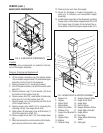
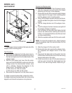
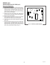
WHIPPER MOTOR
FIG. 8 WHIPPER MOTOR
P1924
Location:
The whipper motor is located on the back side of the
whipper motor mounting panel.
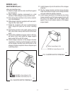
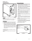
Test Procedure:
1. Disconnect the dispenser from the power source.
2. Disconnect the white/red and white/brown wires of
the main wiring harness from the black leads of the
whipper motor.
3. With the CDS hopper level lower than the probe,
press and hold the SERVICE switch and check the
voltage across the disconnected harness wires
with a voltmeter. Connect the dispenser to the
power source. The indication must be:
a) 120 volts ac for 120 volt models.
b) 230 volts ac for 230 volt CE models.
4. Disconnect the dispenser from the power source.
If voltage is present as described, replace the motor.
If voltage is not present as described, refer to the wiring
diagrams and check the dispenser wiring harness.
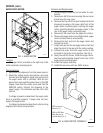
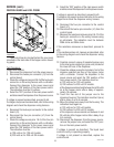
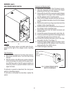
Removal and Replacement:
1. Disconnect the dispenser from the power source.
2. Open the dispenser door and remove the hopper
assembly out the front of the dispenser.
3. Remove the four #8-32 screws securing the hopper
support panel to the auger motor mounting panel
and the whipper motor mounting panel.
4. Slowly lift the hopper support panel up and discon-
nect the red/black and green wires from the hopper
switch.
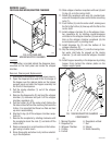
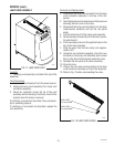
5. Pull the mixing chamber out of the whipper cham-
ber.
6. Twist the whipper chamber clockwise and pull it off
the whipper chamber receptacle.
7. Pull the frother off the motor shaft. Notice the flat
side on the shaft and the matching flat inside the
frother. It is important that these two flats are lined
up when reassembling.
8. Slide the receptacle with seal off of the motor shaft.
NOTE: To remove the receptacle only, rotate clockwise
until the receptacle clears the nuts and slide off of the
motor shaft.
9. Slide the slinger off of the motor shaft.
10. Remove the two nuts securing the whipper cham-
ber receptacle and whipper motor to the front
panel.
11. Disconnect the black leads on the motor from the
white/red and white/brown wires of the main wiring
harness and remove the motor.
12. Install new motor on rear of front panel and secure
with two nuts. Connect the black leads from the
motor to the main wiring harness. Refer to Fig. 9
29793 011500