


19
SERVICE (cont.)
CONTROL BOARD and LEVEL PROBE (cont.)
Test Procedure:
Low Product Detect
1. Disconnect the dispenser from the power source.
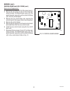
2. Disconnect the twelve pin connector (J1) from the
control board.
3. Check the voltage across pins 2 & 3 of the twelve pin
connector on the wiring harness with a voltmeter.
Connect the dispenser to the power source and
select the "ON" position of the main power switch.
The indication must be 24 volts ac.
4. Select the "OFF" position of the main power switch
and disconnect the dispenser from the power source.
If voltage is present as described, proceed to #5.
If voltage is not present as described, refer to the wiring
diagram and check the dispenser wiring harness.
5. Reconnect the twelve pin connector to the control
board (J1).
6. Disconnect the four pin connector (J6) from the
control board.
7. Check the voltage across pins 1 (positive) & 3
(negative) of the four pin connector on the control
board with a voltmeter. Connect the dispenser to
the power source and select the "ON" position of the
main power switch. The indication must be +5 volts
dc.
8. Select the "OFF" position of the main power switch
and disconnect the dispenser from the power source.
If voltage is present as described, proceed to #9.
If voltage is not present as described, replace the
control board.
9. Reconnect the four pin connector to the control
board (J6).
10. Check the voltage across pins 1 (positive) & 3
(negative) of the four pin connector on the control
board with a voltmeter. Place a full hopper in the
dispenser, connect the dispenser to the power
source, select the "ON" position on the main power
switch, and close the dispenser door. The indica-
tion must be +5 volts dc.
11. Disconnect the dispenser from the power source,
remove the jumper wire, and select the "OFF" posi-
tion on the main power switch.
If voltage is present as described, proceed to #12.
If voltage is not present as described, replace the photo
transistor.
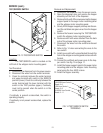
12. Check the voltage across pins 1 (positive) & 3
(negative) of the four pin connector on the control
board with a voltmeter. Remove the hopper from
the dispenser, connect the dispenser to the power
source and select the "ON" position of the main
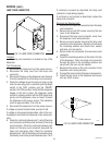
power switch. Shine a flashlight on the photo
transistor (left side panel). The indication must be
less than 1 volt dc.
13. Disconnect the dispenser from the power source
and select the "OFF" position on the main power
switch.
If voltage is present as described, proceed to #14.
If voltage is not present as described, replace the photo
transistor.
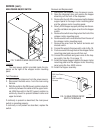
14. Disconnect the two pin connector (J2) from the
control board.
15. Check the voltage across pins 1 (positive) & 2
(negative) of the two pin connector on the control
board with a voltmeter. Connect the dispenser to
the power source and select the "ON" position of the
main power switch. The indication must be +1.5
volts dc.
16. Select the "OFF" position of the main power switch
and disconnect the dispenser from the power source.
If voltage is present as described, proceed to #17.
If voltage is not present as described, replace the
control board.
17. Check the photo LED forward and reverse bias
using a diode tester. The photo LED must be
forward biased with positive applied to pin 1 of the
two pin connector and negative applied to pin 2 of
the two pin connector. The photo LED must be
reverse biased with negative applied to pin 1 of the
two pin connector and positive applied to pin 2 of
the two in connector.
If the photo LED biasing checks as described, the low
level detect circuitry is operating properly.
If the photo LED biasing does not check as described,
replace the photo LED.
NOTE: The photo LED lights in the infrared spectrum
and is not visible to the human eye.
29793 061599