


18
SERVICE (cont.)
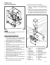
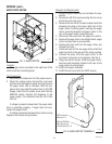
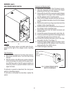
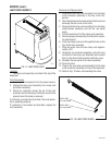
CONTROL BOARD and LEVEL PROBE
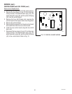
FIG. 11 CONTROL BOARD
P1925
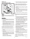
Location:
The control board is located behind the rear panel,
mounted on the back side of the hopper motor mount-
ing panel.
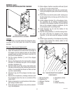
Test Procedure:
Liquid Level Control
1. Disconnect the dispenser from the power source.
2. Disconnect the twelve pin connector (J1) from the
control board.
3. Check the voltage across pins 2 & 3 of the twelve pin
connector on the wiring harness with a voltmeter.
Connect the dispenser to the power source and
select the "ON" position of the main power switch.
The indication must be 24 volts ac.
4. Select the "OFF" position of the main power switch
and disconnect the dispenser from the power source.
If voltage is present as described, proceed to #5.
If voltage is not present as described, refer to the wiring
diagram and check the dispenser wiring harness.
5. Reconnect the twelve pin connector to the control
board (J1).
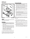
6. Disconnect the four pin connector (J7) from the
control board.
7. Check the voltage across pins 1 & 3 of the four pin
connector on the wiring harness with a voltmeter.
Connect the dispenser to the power source and
select the "ON" position of the main power switch.
The indication must be:
a) 120 volts ac for 120 volt models.
b) 230 volts ac for 230 volt CE models.
8. Select the "OFF" position of the main power switch
and disconnect the dispenser from the power source.
If voltage is present as described, proceed to #9.
If voltage is not present as described refer to the wiring
diagram and check the dispenser wiring harness.
9. Reconnect the four pin connector to the control
board (J7).
10. Disconnect the twelve pin connector (J1) from the
control board.
11. Measure the resistance between pins 8 & 12 of the
twelve pin connector on the wiring harness using
an ohmmeter. The indication must be between
298k ohms and 304k ohms.
If the resistance measures as described, proceed to
#12.
If the resistance does not measure as described, refer
to the wiring diagram and check the dispenser wiring
harness.
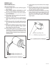
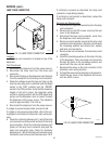
12. Carefully connect a piece of insulated jumper wire
to the level probe contact pin (pink wire) located at
the lower left rear of the dispenser.
13. Check the voltage across the terminals, first of the
dispense solenoid and then of the hopper motor
with a voltmeter. Connect the dispenser to the
power source and select the "ON" position of the
main power switch. The indication must be:
a) 120 volts ac for 120 volt models.
b) 230 volts ac for 230 volt CE models.
at the dispense solenoid and between 4 and 26 volts
dc at the hopper motor after a delay of approxi-
mately 10 seconds.
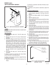
14. Touch the free end of the jumper wire to the
dispenser housing. The indication must be 0 (zero)
after a delay of up to 5 seconds.
15. Move the jumper wire away from the housing. The
indication must again be:
a) 120 volts ac for 120 volt models.
b) 230 volts ac for 230 volt CE models.
at the dispense valve solenoid and between 4 and
26 volts dc at the hopper motor after a delay of up
to 5 seconds.
16. Disconnect the dispenser from the power source,
remove the jumper wire, and select the "OFF" posi-
tion on the main power switch.
If voltage is present as described, The liquid level
control circuitry is operating properly.
If voltage is not present as described, replace the
control board.
29793 011500