


28
SERVICE (cont.)
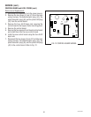
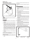
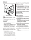
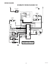
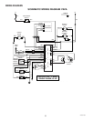
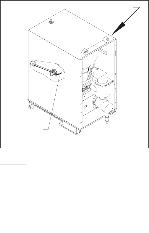
HOPPER LEVEL INDICATOR
FIG. 25 HOPPER LEVEL INDICATOR
P1932
Location:
The photo transistor and LED are located on the
hopper side panels mounted just below the hopper
guide rails.
Test Procedures:
Refer to the section
CONTROL BOARD and LEVEL
PROBE
for test procedures.
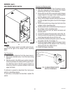
Removal and Replacement:
1. Disconnect the dispenser from the power source
and the water supply.
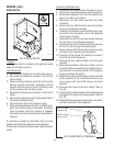
2. Remove the dispenser from the CDS machine and
place it on a flat work surface.
3. Disconnect the door lamp cord from the lamp
connector.
4. Remove the two #8-32 screws securing the door
hinge to the dispenser housing.
5. Carefully pull the door forward until the door sup-
port arms come completely out of the dispenser
housing and set aside.
6. Remove the six #8-32 truss head screws securing
the rear cover to the dispenser housing.
7. Remove the six #8-32 round head screws securing
the front of the housing to the side panels.
8. Remove the six #8-32 truss head screws securing
the back of the housing to the side panels.
9. Carefully lift and spread the housing to remove it
from the rest of the dispenser.
10. Disconnect the photo transistor (J6) or LED (J2)
plug from the control board.
11. Cut the cable tie securing the cable assembly to the
cable tie mount.
12. Gently pull the photo transistor or LED from its
mounting lens.
13. Pull the photo transistor or LED through the grom-
met and free of the dispenser.
14. Snap the photo transistor or LED into the mounting
lens and feed the cable end through the grommet.
15. Gently bend the cable flush to the cable tie mount
and secure with new cable tie. Cut away excess
cable tie.
16. Connect the photo transistor (J6) or LED (J2) plug
to the control board.
17. Reassemble the dispenser top housing, rear panel,
and door assembly to the dispenser.
18. Reconnect the dispenser to the power source and
the water supply.
Photo LED
Photo Transistor
29793 061599