


32
SERVICE (cont.)
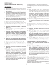
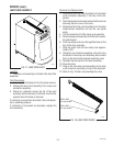
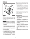
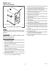
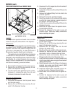
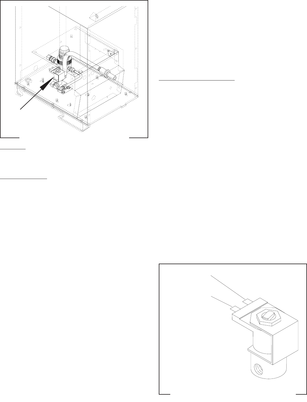
FIG. 31 DISPENSE SOLENOID VALVE
P1935
DISPENSE SOLENOID VALVE
Location:
The dispense solenoid valve is located on the left
side of the dispenser base inside of the rear cover.
Test Procedures:
1. Disconnect the dispenser from the power source.
2. Disconnect the white/red and white/brown wires
from the solenoid valve.
3. Check the voltage across the white/red and white/
brown wires with a voltmeter. Connect the dis-
penser to the power source. The indication must be:
a) 120 volts ac for 120 volt models.
b) 230 volts ac for 230 volt CE models.
4. Disconnect the dispenser from the power source.
If voltage is present as described, proceed to #5.
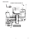
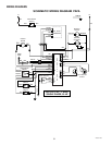
If voltage is not present as described, refer to wiring
diagrams and check the dispenser wiring harness.
5. Check for continuity across the solenoid valve coil
terminals.
If continuity is present as described, reconnect the
white/red and white/brown wires to the solenoid.
If continuity is not present as described, replace the
solenoid valve.
6. Check the solenoid valve for coil action. Connect
the dispenser to the power source. Press the dis-
pense switch and listen carefully for a "clicking"
sound as the magnet attracts.
7. Disconnect the dispenser from the power source.
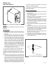
If the sound is heard as described and water will not
pass through the solenoid valve, there may be a block-
age in the water line before the solenoid valve or, the
solenoid valve may require inspection for wear and the
removal of waterborne particles.
If the sound is not heard as described, replace the
solenoid valve.
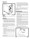
Removal and Replacement:
1. Disconnect the dispenser from the power source
and the water supply.
2. Remove the six #8-32 screws securing the rear
panel to the dispenser.
3. Remove the white/red and white/brown wires from
the solenoid valve.
4. Disconnect the water lines to and from the solenoid
valve.
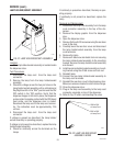
5. Remove the two #8-32 nuts securing the solenoid
mounting bracket to the dispenser base. Remove
the solenoid and bracket assembly.
6. Remove the two #10-32 screws and lockwashers
securing the solenoid valve to the bracket.
7. Install a new solenoid valve to the bracket using two
#10-32 screws and lockwashers.
8. Install the solenoid and bracket to the base and
secure with two #8-32 nuts.
9. Install the water lines to and from the solenoid valve
using pipe thread sealant (BOM #M2526.0000) and
tighten securely.
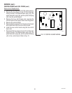
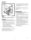
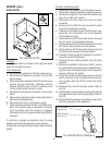
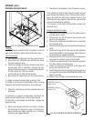
10. Refer to Fig. 32 when reconnecting the wires.
FIG. 32 DISPENSE SOLENOID TERMINALS
P1909
WHI/RED to Control
Board (J7-2)
WHI/BRN to Control
Board (J7-4)
29793 011500