


27
SERVICE (cont.)
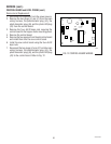
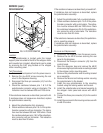
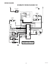
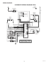
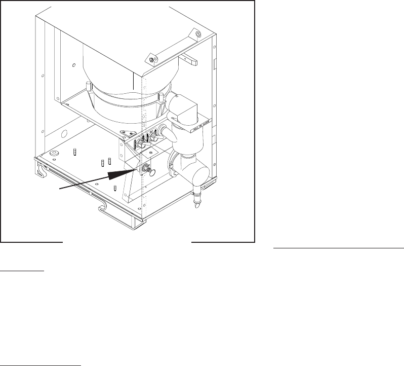
POTENTIOMETER
FIG. 24 POTENTIOMETER
P1931
Location:
The potentiometer is located under the hopper
support panel mounted to the left of the whipper motor
and mounted on a bracket. Adjustments can be made
by removing the 0.50" plug located on the whipper
motor mounting panel.
Test Procedures:
1. Disconnect the dispenser from the power source.
2. Remove the six #8-32 screws securing the rear
cover to the dispenser housing.
3. Disconnect the three pin connector (J3) from the
control board.
4. Check the resistance between pins 1 & 3 of the
potentiometer connector using an ohmmeter. The
indication must be between 800 and 1200 ohms.
If the resistance measures as described, proceed to #5.
If resistance does not measure as described, replace
the potentiometer assembly.
5. Adjust the potentiometer fully clockwise.
6. Check resistance between pins 2 & 3 of the poten-
tiometer connector with an ohmmeter. The indica-
tion must be between 800 and 1200 ohms. Check
the resistance between pins 1 & 2 of the potentiom-
eter connector with an ohmmeter. The indication
must be less than 20 ohms.
If the resistance measures as described, proceed to #7.
If resistance does not measure as described, replace
the potentiometer assembly.
7. Adjust the potentiometer fully counterclockwise.
8. Check resistance between pins 1 & 2 of the poten-
tiometer connector with an ohmmeter. The indica-
tion must be between 800 and 1200 ohms. Check
the resistance between pins 2 & 3 of the potentiom-
eter connector with an ohmmeter. The indication
must be less than 20 ohms.
If the resistance measures as described, the potentiom-
eter is operating properly.
If resistance does not measure as described, replace
the potentiometer assembly.
Removal and Replacement:
1. Disconnect the dispenser from the power source.
2. Remove the six #8-32 screws securing the rear
panel to the dispenser.
3. Disconnect the three pin connector (J3) from the
control board.
4. Open the dispenser door and remove the #8-32
screw securing the potentiometer mounting bracket
to the whipper motor mounting panel.
5. Remove the potentiometer and mounting bracket
as an assembly.
6. Remove the facenut and locking washer securing
the potentiometer to the bracket.
7. Install the new potentiometer to the mounting
bracket using the locking washer and facenut.
8. Install the potentiometer and bracket assembly to
the whipper motor panel and secure with #8-32
screw.
9. Connect the three pin connector (J3) to the control
board.
10. Install the rear panel to the housing and secure with
six #8-32 screws.
29793 061599