


30
SERVICE (cont.)
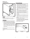
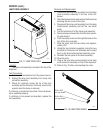
DOOR SWITCH
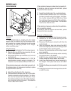
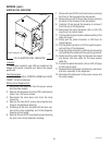
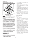
FIG. 28 DOOR SWITCH
P1934
Location:
The door switch is located on the right side panel
under the housing top cover.
Test Procedures:
1. Disconnect the dispenser from the power source.
2. Disconnect the twelve pin connector (J1) from the
control board.
3. Check continuity between pins 8 & 9 on the wiring
harness using an ohmmeter. Continuity must be
present when the door is closed. Continuity must
not be present when the door is open.
4. Reconnect the twelve pin connector to the control
board.
5. Gain access to the door switch using steps listed in
Removal and Replacement
.
6. Disconnect the wires from the door switch.
7. Check continuity between the N.O. and COM. termi-
nals of the switch using an ohmmeter. Continuity
must be present when the actuator is engaged.
Continuity must not be present when the actuator is
released.
If continuity is present as described, refer to wiring
diagram and check the dispenser wiring harness.
If continuity is not present s described, replace the door
switch.
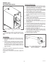
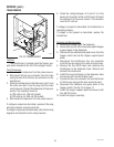
Removal and Replacement:
1. Disconnect the dispenser from the power source.
2. Remove the hopper assembly from the dispenser.
3. Remove the dispenser from the CDS machine and
place it on a flat work surface.
4. Disconnect the door lamp cord from the lamp
connector.
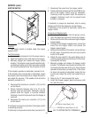
5. Remove the two #8-32 screws securing the door
hinge to the dispenser housing.
6. Carefully pull the door forward until the door sup-
port arms come completely out of the dispenser
housing and set aside.
7. Remove the six #8-32 truss head screws securing
the rear cover to the dispenser housing.
8. Remove the six #8-32 round head screws securing
the front of the housing to the side panels.
9. Remove the six #8-32 truss head screws securing
the back of the housing to the side panels.
10. Carefully lift and spread the housing to remove it
from the rest of the dispenser.
11. Remove the door switch actuator from the nylon
standoff.
12. Noting the orientation of the door switch, remove
the two #6-32 screws and the nylon standoff secur-
ing the switch mounting bracket to the dispenser
housing. Remove the switch.
13. Attach the new door switch taking care to orient the
switch correctly in the mounting bracket and se-
cure in place with two #6-32 screws and nylon
standoff.
14. Reconnect the wires to the door switch. Refer to
Fig. 29.
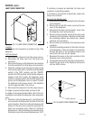
15. Install the door switch actuator orienting the notched
side against the right side housing panel. Refer to
Fig. 28.
16. Reassemble the dispenser top housing, rear panel,
and door assembly to the dispenser.
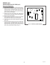
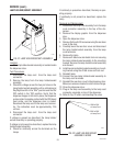
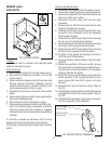
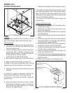
FIG. 29 DOOR SWITCH TERMINALS
P1908
ACTUATOR
ORA to Control
Board (J1-9)
GRN to Control
Board (J1-8)
29793 061599