14
Important: To the Operator
Models QS12 & QS24
071102
Section 5 Important: To the Operator
MENU
UF
TIME
TEMP
UP
DOWN
EXIT
UM
UR
LR
LM
LF
MANUFACTURED BY THE TAYLOR COMPANY
ROCKTON, ILLINOIS U.S.A.
4
3
2
1
I
0
5
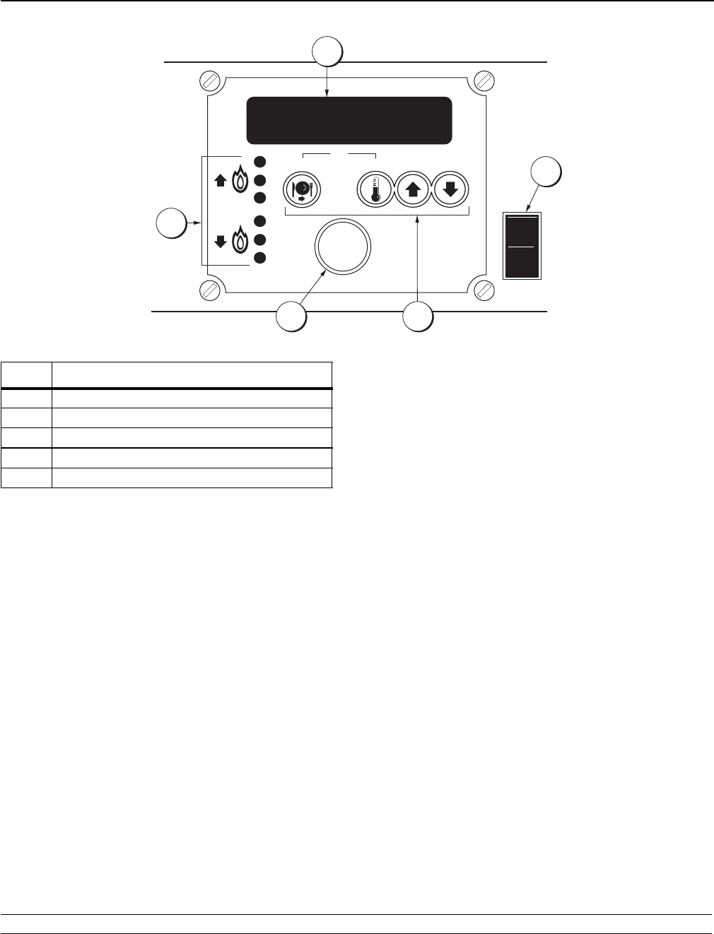
ITEM DESCRIPTION
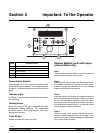
1 Power Switch
2 Keypads
3 LED Display
4 Indicator Lights
5 Timer Button
Power Switch (Rocker)
When placed in the “ON” position, the power switch
allows control panel operation for the applicable side
of the grill. The power switches are located on the front
panel.
Indicator Light
The lights on the front panel indicate when the heaters
are operating.
Heating Zones
Each side (zone) of the grill is equipped with three
independent heating elements. The i ndependent
elements assure even temperatures and quick
temperature recovery.
Timer Button
Used to s tart and s top the cook timer.
Release Material (units with upper
cook surfaces only)
Step 1
Lay the release material sheet on the lower plate and
carefully lower the upper cook surface.
Step 2
Starting with the spring side, slide the straight end of
the release material rod through the front spring,
continue through the hemmed end of the release
sheet, and through the rear s pring.
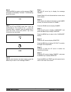
Step 3
Insert the second rod through the opposite hemmed
side of the release material sheet. Grasp both ends of
the rod, pull the release material up and around the
non-spring side of the upper cook surface and attach
the rod ends to the retaining clips. Turn the rods so that
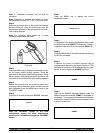
the hooked end is facing downward.
Step 4
Raise the upper cook surface and assure that the
release material sheet fits evenly and snugly on the
upper cook surface. Rotate the release material sheet
on an every other day basis.


