


14
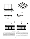
ASSEMBLE THE ROOF CURB — Connect the curb side
and the curb end. Insert the tabs on the curb end into the slots
on the curb sides. See Fig 6. Press firmly until the pieces lock
in to place. It may be necessary to exert additional force to the
top of the curb to lock the pieces in place. Ensure the curb piec-
es are locked together prior to proceeding. Repeat for other cor-
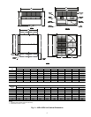
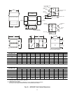
ners of the roof curb. See Fig. 7 and 11 for roof curb dimen-
sions.
NOTE: If lifting or moving the roof curb assembly hammer
the tabs over 90 degrees.
SET THE ROOF CURB — Fit the roof curb assembly by
measuring across the corners of the curb to ensure a square fit.
Level the curb by placing shims under the bottom flange of the
curb. Secure the curb in place by welding or fastening the curb
to the roof.
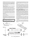
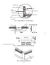
INSTALL ROOFING MATERIALS — Insulate and add a
cant strip to the roof curb. Follow suggested and acceptable
roofing procedures for applying roofing materials. The roofing
material should extend up to the wood nailer and be secured
under the counter flashing. Follow all local, national, and in-
dustry roofing standards. Refer to Fig. 4 for roofing recommen-
dations.
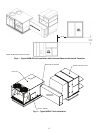
INSTALL THE HORIZONTAL BASE (62EB-EU UNITS
ONLY) — Remove the fork pockets from the bottom of the
horizontal base. After removing the fork pockets from the bot-
tom of the horizontal base place the base on the roof curb. Se-
cure the horizontal base to the curb using no. 14, 2-in. self-tap-
ping sheet metal screws.
Apply the factory provided gasketing material to the top
of the horizontal base. Follow the rigging directions in the
Step 6 — Rig and Place Unit section to place the ERV on the
horizontal base. Position the ERV so that the ERV's LCD dis-
play is on the opposite side of the horizontal base's duct open-
ings. Secure the ERV to the horizontal base using 1-in. self-tap-
ping sheet metal screws every 18 in. around the perimeter.
NOTE: The ERV may also be mounted to the horizontal base
prior to being set on the roof curb.
INSTALL THE HORIZONTAL TRANSITION — Apply
the factory-provided gasketing material to the horizontal transi-
tion at all points where duct connections are made. Attach the
horizontal transition to the horizontal base (62EB-EU units) or
the ERV (62E2-E7 units) and RTU return connection using
1-in. self-tapping sheet metal screws. Ensure that all connec-
tions are water and air tight.
Step 5 — Install Standard Roof Curb
VERTICAL STAND-ALONE APPLICATIONS (62EB-
EU UNITS) — The ERV unit can be installed without being
coupled with a RTU. The ERV units can be installed in one of
two stand-alone applications: vertical discharge or horizontal
discharge. Vertical discharge requires the use of a standard roof
curb. When installing a stand-alone ERV in a vertical applica-
tion complete the following steps:
Locate the Roof Curb
— Prior to locating the roof curb
consider the structural support required for the rooftop system
and, the duct drop location in relation to the joists. Allow suffi-
cient space for service, clearance, and locations of vents or
other sources of air. Refer to Fig. 2 and 3 for ERV clearance
requirements.
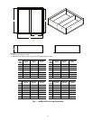
Assemble the Roof Curb
— Connect the curb side and the
curb end. Insert the tabs on the curb end into the slots on the
curb sides. See Fig. 6. Press firmly until the pieces lock into
place. It may be necessary to exert additional force to the top of
the curb to lock the pieces in place. Ensure the curb pieces are
locked together prior to proceeding. Repeat for all corners of
the roof curb.
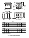
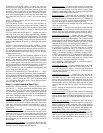
Prepare Roof Curb Location
— Cut a hole in the roof for duct
openings. See Fig. 7 for duct opening dimensions. Frame the
opening to provide adequate structural support.
Set the Roof Curb
— Fit the roof curb assembly by measuring
across the corners of the curb to ensure a square fit. Set the roof
curb over the roof opening. Level the curb by placing shims
under the bottom flange of the curb. Secure the curb in place by
welding or fastening the curb to the roof.
Install Ductwork
— Ductwork will be installed in the roof
curb for vertical discharge stand-alone applications. The duct
will hang from the top of the curb. Refer to Fig. 7 to determine
the duct size required. Provide field manufactured duct and
place into the supply and return openings in the curb.
NOTE: Ductwork must be installed in the ERV curb before the
ERV unit is set in place.
Install Gaskets
— The ERV roof curbs come with a gasketing
package to provide a seal between the ERV unit and the top pe-
rimeter of the roof curb. Install the gasket around the top pe-
rimeter of the curb and around the supply and return opening.
Install Roofing Materials
— Insulate and add a cant strip to
the roof curb. Follow suggested and acceptable roofing
practices for applying roofing materials. The roofing material
should extend up to the wood nailer and be secured under the
counterflashing. Follow all local, national, and industry roofing
standards. Refer to Fig. 4 for roofing recommendations.
HORIZONTAL STAND-ALONE APPLICATIONS (62EB-
EU and 62E2-E7 Units) — The ERV unit can be installed
without being coupled with a RTU. The ERV units can be in-
stalled in one of two stand-alone applications: vertical dis-
charge or horizontal discharge. Horizontal discharge with a
62EB-EU units requires the use of the horizontal base accesso-
ry. The horizontal base accessory include a horizontal dis-
charge box and a roof curb to support the box. The horizontal
base accessory is not required with 62E2-E7 units.
When installing a stand-alone ERV in a horizontal applica-
tion complete the following steps:
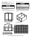
Locate the Roof Curb
— Prior to locating the roof curb con-
sider the structural support required for the rooftop system. Al-
low sufficient space for service, clearance, and locations of
vents or other sources of air. Refer to Fig. 2, 3, and 10 for ERV
clearance requirements.
Assemble the Roof Curb
— Connect the curb side and the
curb end. Insert the tabs on the curb end into the slots on the
curb sides. See Fig 6. Press firmly until the pieces lock into
place. It may be necessary to exert additional force on top of
the curb to lock the pieces in place. Ensure the curb pieces are
locked together prior to proceeding further. Repeat for other
corners of the roof curb. See Fig. 7 and 11 for roof curb dimen-
sions.
NOTE: If lifting or moving the roof curb assembly, hammer
the tabs over 90 degrees.
Set the Roof Curb
— Fit the roof curb assembly by measuring
across the corners of the curb to ensure a square fit. Level the
curb by placing shims under the bottom flange of the curb. Se-
cure the curb in place by welding or fastening the curb to the
roof.
Install Roofing Materials
— Insulate and add a cant strip to
the roof curb. Follow suggested and acceptable roofing proce-
dures for applying roofing materials. The roofing material
should extend up to the wood nailer and be secured under the
counter flashing. Follow all local, national, and industry roof-
ing standards. Refer to Fig. 4 for roofing recommendations.
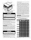
Install the Horizontal Base (62EB-EU Units Only)
— Re-
move the fork pockets from the bottom of the horizontal base.
After removing the fork pockets, place the base on the roof
curb. Secure the horizontal base to the curb using no. 14, 2-in.
self-tapping sheet metal screws.