


7
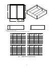
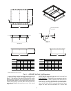
ASSEMBLE THE ERV ROOF CURB — Connect the curb
side and the curb end. Insert the tabs on the curb end into the
slots on the curb sides. See Fig. 6. Press firmly until the pieces
lock into place. It may be necessary to exert additional force on
top of the curb to lock the pieces in place. Ensure the curb piec-
es are locked together prior to proceeding further. Repeat for
other corners of the roof curb.
NOTE: If lifting or moving the roof curb assembly, hammer
the tabs over 90 degrees.
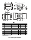
PREPARE ROOF CURB LOCATION — Cut a hole in the
roof for duct openings. See Fig. 7 for duct opening dimensions.
Frame the opening to provide adequate structural support.
SET THE ERV ROOF CURB — Fit the roof curb assembly
by measuring across the corners of the curb to ensure a square
fit. Set the roof curb over the roof opening. Level the curb by
placing shims under the bottom flange of the curb. Secure the
curb in place by welding or fastening the curb to the roof.
INSTALL DUCTWORK — Ductwork will be installed in the
ERV roof curb for applications utilizing the drop-in damper
box. The duct will hang from the top of the curb. Refer to
Fig. 7 to determine the duct size required. Provide field-
manufactured duct and place into the supply and return open-
ings in the curb.
NOTE: Ductwork must be installed in the ERV curb before the
ERV unit is set in place.
NOTE: Drop-in damper box must be installed in the RTU curb
before the RTU is set in place.
INSTALL GASKETS — The ERV roof curbs come with a
gasketing package to provide a seal between the ERV unit and
the top perimeter of the roof curb. Install the gasket around the
top perimeter of the curb and around the supply and return
opening. Gasket strips must fit tightly together, leaving no gaps
for leakage.
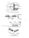
INSTALL ROOFING MATERIALS — Insulate and add a
cant strip to the roof curb. Follow suggested and acceptable
roofing procedures for applying roofing materials. The roofing
material should extend up to the wood nailer and be secured
under the counter flashing. Follow all local, national, and in-
dustry roofing standards. Refer to Fig. 4 for roofing recommen-
dations.
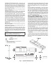
INSTALL DROP-IN DAMPER BOX — Place the damper
box into the RTU curb. Allow the damper box flanges to rest
on the curb. Secure the damper box in place with 1-in. self-tap-
ping screws. Install ductwork to connect the damper box to the
ERV curb. The upper damper box connection must be ducted
to the ERV supply air, and the lower damper box connection
must be ducted to the ERV exhaust air. See Fig 5. Refer to the
drop-in damper box dimensional sheets to determine the duct
size required. Your local Carrier sales representative can pro-
vide you with this dimensional data.
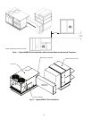
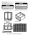
Step 4 — Install Horizontal Base and Transi-
tion (62EB-EU and 62E2-E7 Units) —
The hori-
zontal transition accessory is used to connect the ERV to the
horizontal return of a Carrier rooftop unit. To provide horizon-
tal exhaust and ventilation air connections on 62EB-EU units,
the horizontal base accessory must also be installed. The acces-
sory is not needed on 62E2-E7 units. The rooftop unit must be
installed on a standard 14 in. high roof curb and positioned at a
specific distance relative to the ERV base. A typical arrange-
ment is shown in Fig. 8 and 9. See Fig. 10 for 62E2-E7 unit di-
mensions. Your local Carrier sales representative can provide
you with dimensional data for the appropriate Carrier RTU and
62E model installation.
LOCATE THE ROOF CURB — Prior to locating the roof
curb consider the structural support required for the rooftop
system. Allow sufficient space for service, clearance, and loca-
tions of vent or other sources of air. Refer to Fig. 2, 3, and 10
for ERV clearance requirements. Refer to the rooftop installa-
tion instructions for more information regarding location
considerations.
Proper location of the roof curb in relationship to the RTU
roof curb is critical for proper fit of the horizontal transition.
See Fig. 8 and 9. Refer to the ERV unit submittals provided by
your local Carrier sales representative for the correct
dimensions.
IMPORTANT: Gasket installation is critical for water
integrity. Improperly installed gaskets can result in air or
water leaks, leading to poor unit performance.
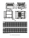
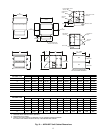
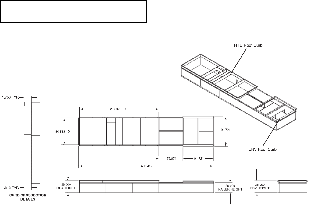
Fig. 1 — Typical Combination Curb
LEGEND
NOTES:
1. Return air ductwork sits 12 in. below bottom of
curb. (Stub duct provided.)
2. Dimensions shown in inches.
ERV — Energy Recovery Ventilator
RTU — Rooftop Unit