


27
MOTORIZED DAMPERS — Units may have an optional
two-position outside-air damper, exhaust-air damper, or both.
The dampers will modulate closed when the ERV is off.
MODULATING CO
2
CONTROL — The supply fan speed
will be modulated to provide supply airflow between minimum
and maximum levels based on a programmed indoor CO
2
level.
BUILDING PRESSURE CONTROL — The exhaust fan
speed will be modulated to provide supply airflow between
minimum and maximum levels based on a programmed indoor
building pressure.
ERV UNIT WITH ECONOMIZER, STOP JOG AND
EXHAUST BLOWER RUNNING — This option is used
when the RTU is equipment with an economizer without pow-
er exhaust. When the RTU opens the economizer to provide
free cooling, the ERV supply fan will turn off. The ERV wheel
will be periodically rotated to prevent build-up of contaminates
on the wheel. The ERV exhaust fan will continue to operate.
ERV UNIT WITH ECONOMIZER; ERV DOES NOT
RUN — This option is used when the RTU is equipped with
an economizer with power exhaust. When the RTU opens the
economizer to provide free cooling, the ERV supply and ex-
haust fans will turn off. The ERV wheel will also be turned off.
ComfortLink™ Interface Device — The purpose of
the device is to provide factory-installed “Plug and Play” con-
trol interface between the 62E and a Carrier rooftop unit Com-
fortLink control system. The interface allows for optimal sys-
tem operation by sharing unit data and properly coordinating
energy recovery, economizer, and power exhaust operation.
For HVAC units with electro-mechanical controls, damper
end switches or relays may be used to coordinate the econo-
mizer and power exhaust operation with the ERV. On units
with Com fortLink controls, this becomes more of a challenge
since the economizer and power exhaust sequencing is deter-
mined through software logic and not electromechanical devic-
es. The ComfortLink interface device allows the 62E controls
to read key data points and force critical operating parameters
in the 48/50A unit’s ComfortLink logic to ensure proper sys-
tem operation. The factory-installed option includes a pre-
programmed translator that allows the 62E controller to access
the ComfortLink controls through the unit’s LEN (local
equipment network) plug.
Optional BACnet or LON Communications
Interface —
The BACnet* Communication interface and
LON (local operating network) communications interface
options use the UPC Open controller. The controller
communicates using BACnet on an MS/TP network segment
communications at 9600 bps, 19.2 kbps, 38.4 kbps, or 76.8
kbps.
WIRING — Wire the controllers on an MS/TP network seg-
ment in a daisy-chain configuration. Wire specifications for the
cable are 22 AWG (American Wire Gage) or 24 AWG, low-ca-
pacitance, twisted, stranded, shielded copper wire. The maxi-
mum length is 2000 ft.
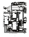
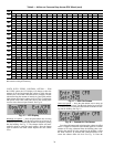
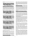
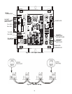
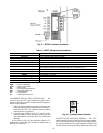
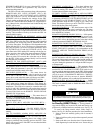
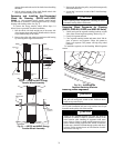
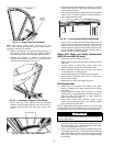
Install a BT485 terminator on the first and last controller on
a network segment to add bias and prevent signal distortions
due to echoing. See Fig. 25-27.
To wire the UPC Open controller to the BAS (buidling au-
tomation system) network:
1. Pull the screw terminal connector from the controller's
BAS Port.
2. Check the communications wiring for shorts and
grounds.
3. Connect the communications wiring to the BAS port’s
screw terminals labeled Net +, Net -, and Shield.
NOTE: Use the same polarity throughout the network
segment.
4. Insert the power screw terminal connector into the UPC
Open controller's power terminals if they are not current-
ly connected.
5. Verify communication with the network by viewing a
module status report. To perform a module status report
using the BACview keypad/display unit, press and hold
the “FN” key then press the “.” Key.
To install a BT485 terminator, push the BT485, on to the
BT485 connector located near the BACnet connector.
NOTE: The BT485 terminator has no polarity associated with
it.
To order a BT485 terminator, consult Commercial Products
i-Vu
®
Open Control System Master Prices.
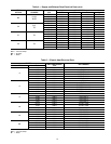
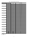
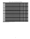
MS/TP WIRING RECOMMENDATIONS — Recommen-
dations are shown in Tables 7 and 8. The wire jacket and UL
temperature rating specifications list two acceptable alterna-
tives. The Halar specification has a higher temperature rating
and a tougher outer jacket than the SmokeGard specification,
and it is appropriate for use in applications where the user is
concerned about abrasion. The Halar jacket is also less likely to
crack in extremely low temperatures.
NOTE: Use the specified type of wire and cable for maximum
signal integrity.
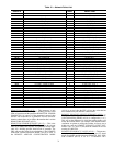
Table 7 — UPC Open System Wiring Specifications and Recommended Vendors
LEGEND
WIRING SPECIFICATIONS RECOMMENDED VENDORS AND PART NUMBERS
Wire Type Description
Connect Air
International
Belden RMCORP
Contractors
Wire and Cable
MS/TP
Network (RS-485)
22 AWG, single twisted shielded pair, low capacitance, CL2P,
TC foam FEP, plenum rated. See MS/TP Installation Guide for
specifications.
W221P-22227 — 25160PV CLP0520LC
24 AWG, single twisted shielded pair, low capacitance, CL2P,
TC foam FEP, plenum rated. See MS/TP Installation Guide
for specifications.
W241P-2000F 82841 25120-OR —
Rnet 4 conductor, unshielded, CMP, 18 AWG, plenum rated. W184C-2099BLB 6302UE 21450 CLP0442
AWG — American Wire Gage
CL2P — Class 2 Plenum Cable
CMP — Communications Plenum Rated
FEP — Fluorinated Ethylene Polymer
TC — Tinned Copper
* Sponsored by ASHRAE (American Society of Heating, Refrigerat-
ing, and Air Conditioning Engineers).