


22
START-UP
Use the following information to check unit PRIOR to start-up.
Unit Preparation — Check that the unit has been in-
stalled in accordance with these installation instructions and all
applicable codes.
Check all fasteners and set screws for tightness. Verify that
all of the panels are in place and secure. Verify that any open-
ings to the ERV cabinet are clear of foreign materials.
Internal Wiring — Check all electrical connections in the
control box. Tighten as required.
Rain Hoods — The outside air hood will include alumi-
num water entrainment filters, which should be in place prior
to starting the unit.
Energy Recovery Wheel
DRIVE BELT — Turn the energy recovery wheel by hand to
verify free operation. Inspect the belt, which drives the energy
wheel rotation. Make sure the belt rides smoothly through the
pulley and over the wheel rim.
AIR SEALS — Check that the air seals located around the
outside of the wheel and across the center, on both sides of the
wheel, are secure and in good condition. Air seals which are
too tight will prevent proper rotation of the energy recovery
wheel.
Air seal clearance may be checked by placing a sheet of pa-
per, like a feeler gage, against the wheel face. To adjust the air
seals, loosen all eight seal retaining screws. These screws are
located on the bearing support that spans the length of the
cassette through the wheel center. Tighten the screws so the air
seals tug slightly on the sheet of paper as the wheel is turned.
Re-check the air seals for tightness after adjustment.
Replace the access door and apply power. Check that the
wheel rotates freely. If the wheel does not rotate or is binding,
remove the cassette and adjust.
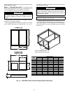
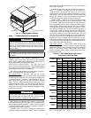
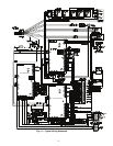
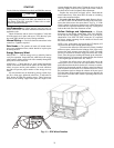
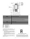
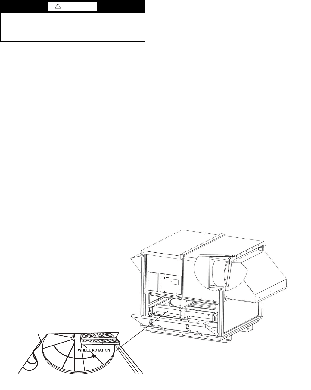
For units with three phase power only: Remove the ser-
vice door to make sure the wheel is turning in the same direc-
tion as the sticker next to the motor shows. See Fig. 15. If the
wheel is turning in the wrong direction turn, off the disconnect
switch and have a qualified electrician swap any 2 of the power
leads on the load side of the disconnect switch.
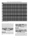
Airflow Settings and Adjustments — With the
disconnect on, the display should show "ERV FAN SPEED"
on the top line of the display. The bottom line of the display
should show "OA=XXX EX=XXX" where the “X”s represent
the blower output percentage for the outside air blowers and
the exhaust air blowers.
NOTE: If any of the alarms are tripped, the LCD display will
scroll between the alarms and the normal display.
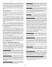
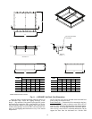
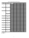
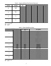
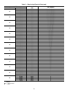
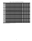
To measure the airflow the ERV units have factory-installed
airflow test ports, which allow the balancer of the job to easily
measure the static pressure across the ERV wheel. The static
pressure is measured on both the supply and return sides of the
wheel. Take this pressure reading and match up the wheel dif-
ferential pressure ( P) to pressure chart to display the cfm that
is flowing through the ERV wheel. See Table 6.
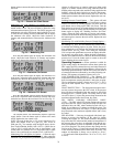
To balance the airflow remove the small panel next to the
control panel cover to access the user input controls. Press the
push button and turn the knob clockwise to increase or counter-
clockwise to decrease the outside air blower speed (use the test
ports and charts described above to calculate cfm levels). Press
the push button again to change the exhaust air blower speed.
Press the button again to return to the main screen. Replace the
user control cover when ERV cabinet is operating at the correct
blower speeds.
CAUTION
Before turning the disconnect switch on, verify that the
voltage being provided to the ERV unit matches the volt-
age shown on the ERV nameplate. Failure to do so could
result in equipment damage.
Fig. 15 — ERV Wheel Rotation
a62-383.eps