


33
engages the notch at the end of the shaft when reinstalling
the wheel.
4. Pull the wheel straight off the shaft. Handle wheel with
care to prevent distorting of the wheel.
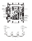
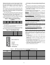
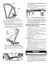
Removing and Installing Non-Segmented
Wheel for Cleaning (62ECC and 62E2C
Units) — Non-segmented energy transfer wheels include
the shaft and are secured to 2 wheel support beams by 2 flange
bearings with locking collars. See Fig. 31.
To remove the energy transfer wheel, follow Steps 1-4
below. Reverse procedure for wheel installation.
1. Pull the wheel with shaft straight out of the motor side
wheel support beam and bearing. Handle wheel with care
to prevent distorting of the wheel.
2. Remove the pulley side wheel support beam with bearing
by removing the 4 support beam screws.
3. Remove the belt from the pulley and position temporarily
around the wheel rim.
4. Loosen the 2 set screws on each of the 2 wheel bearings.
See Fig. 31.
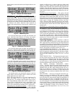
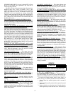
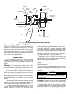
Removing Wheel Segments for Cleaning
(62ECD, 62ED-EU, 62E2D, and 62E3-E6 Units)
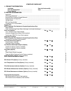
1. Unlock and open the segment retaining brackets on both
sides of the selected segment opening. Refer to Fig. 32.
2. Gently lift segment outward.
3. Close segment retaining latches and rotate wheel 180 de-
grees to remove next segment. Follow this pattern to
remove all segments. This pattern will help keep wheel
balanced.
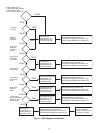
To install the segments, see the Installing Wheel Segments
section.
Installing Wheel Segments
NOTE: Both installation and removal procedures must be per-
formed from the pulley side of the cassette.
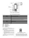
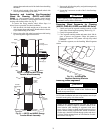
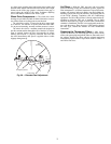
Alignment
Pin
Cassette
Housing/Frame
Shaft
Bearings (2)
Hub Cover
Wheel &
Hub
Fig. 30 — 62EB and 62E7 Energy
Transfer Wheel Assembly
A62-279ef
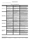
FLANGE
BEARINGS
(2)
SET
SCREWS
(2) EACH
WHEEL,
HUB &
SHAFT
WHEEL SUPPORT BEAMS
Fig. 31 — 62ECC and 62E2C Energy
Transfer Wheel Assembly
CAUTION
When replacing wheel, retighten the 4 bearing set screws.
Premature bearing failure could result.
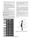
WARNING
Before performing service or maintenance operations on
unit, turn off main power switch to unit. Electrical shock
could cause personal injury.
CAUTION
Weight of the installed segment will cause the wheel to
accelerate in rotation. Failure to maintain control of the
wheel rotation while installing all segments could cause
severe injury to fingers or hand caught between revolving
spokes and the bearing support beam. Handle of hammer,
or other stop, should be inserted through spokes and above
or below bearing support beams to limit rotation of unbal-
anced wheel. See Fig. 33.
Fig. 32 — Unlocking the
Segment Retaining Brackets
A62-278ef