


25
button again to return to the main screen. Replace the user con-
trol cover.
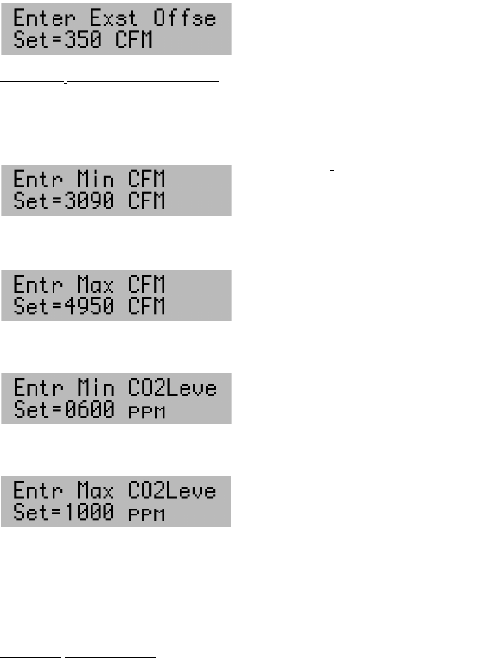
Modulating CO
2
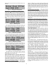
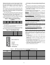
with Balanced Air Option (Fig. 20) —
This option allows the user to enter minimum and maximum
outside airflow levels. The user will then be allowed to enter
minimum and maximum CO
2
levels. The EzERV program will
modulate the cfm of the ERV based on the building CO
2
level.
To enter the user settings press the pushbutton once to display
the minimum cfm screen. Adjust the knob clockwise to
increase and counterclockwise to decrease the minimum cfm
level.
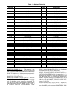
Press the push button again to display the maximum cfm
screen. Adjust the knob clockwise to increase and counter-
clockwise to decrease the maximum cfm level. See Fig. 21.
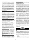
Press the push button again to display the minimum CO
2
level screen. Adjust the knob clockwise to increase and coun-
terclockwise to decrease the minimum CO
2
level. See Fig. 22.
Press the push button again to display the maximum CO
2
level screen. Adjust the knob clockwise to increase and coun-
terclockwise to decrease the maximum CO
2
level. See Fig. 23.
The exhaust airflow will automatically adjust to equal the
supply airflow. Press the button again to return to the main
screen. Replace the user control cover.
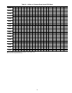
NOTE: The scale for the cfm vs. CO
2
level is based on a CO
2
sensor that outputs 0-vdc at 0 ppm CO
2
and 10-vdc at
2000 ppm CO
2
. For example, using the figures above, the air-
flow would modulate linearly from 1458 L/s (3090 cfm) at
3vdc to 2336 L/s (4950 cfm) at 5-vdc. A signal below 3-vdc
would result in a constant 1458 L/s (3090 cfm) while a signal
above 5-vdc would result in a constant 2336 L/s (4950 cfm).
Modulating CO
2
with Offset Air Option — Follow the steps
above for modulating CO
2
with balanced air. After setting the
maximum CO
2
level press the push button again to display the
exhaust air offset screen. A negative exhaust air offset would
equate to a smaller amount of air being exhausted from the
building when compared to the outside air being supplied to the
building. Adjust the knob clockwise to increase and counter-
clockwise to decrease the exhaust offset cfm level. Press the
button again to return to the main screen. Replace the user con-
trol cover.
Building Pressure Control Option
— This option will hold
the outside air cfm level constant and will modulate the exhaust
airflow to maintain the building pressure set point. Press the
push button once to bring up the ERV cfm screen. Turn the
knob clockwise to increase or counterclockwise to decrease the
amount of outside air coming into the building. Press the push
button again to display the "Building Pressure Set Point"
screen. Adjust the knob clockwise to increase and counter-
clockwise to decrease the desired building pressure level. Press
the button again to return to the main screen. Replace the user
control cover.
Modulating CO
2
with Building Pressure Control Option —
This option will modulate the supply fan of the ERV based on
the building CO
2
level, and will modulate the exhaust airflow
to maintain the building pressure set point. Follow the proce-
dure outlined above to configure the minimum and maximum
outside airflow and CO
2
levels. After setting the maximum
CO
2
level press the push button once more to display the build-
ing pressure set point screen. Adjust the knob clockwise to
increase and counterclockwise to decrease the desired building
pressure level. Press the button again to return to the main
screen. Replace the user control cover.
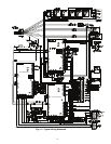
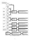
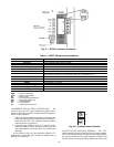
Operating Sequence — When operation is called for
by the rooftop supply fan interlock or remote timer option, the
ERV supply blower(s), exhaust blower(s) and wheel motor will
be energized. The supply and exhaust blowers will provide the
adjusted/programmed airflow and the ERV wheel will rotate at
a constant speed unless influenced by one of the following con-
ditions. The sequence of operation is shown in Fig. 24.
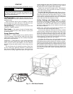
LOW TEMPERATURE LOCKOUT — The optional low
temperature lockout function locks out the 62E ERV if the out-
door-air temperature entering the wheel is below the set point.
The low temperature lockout is factory set at –23.3 C (–10 F),
and can be field adjusted from –34.4 C to 37.8 C (–30 F to
100 F).
FROST PROTECTION — The frost protection option moni-
tors the pressure drop across the ERV wheel. If the pressure
drop rises above an adjustable limit, the outside air fan will be
de-energized for a 5-minute period. The setting must be field
set at 50% above (1.5 times) the pressure drop measured at the
maximum adjusted airflow and a clean, dry wheel.
ERV WHEEL VARIABLE FREQUENCY DRIVE
(VFD) — The ERV wheel VFD option monitors the pressure
drop across the ERV wheel. If the pressure drop rises above an
adjustable limit, the ERV wheel rotational speed will be re-
duced for a minimum of 5 minutes to defrost the wheel. The
setting must be field set at 50% above (1.5 times) the pressure
drop measured at the maximum adjusted airflow and a clean,
dry wheel.
PRE-HEATERS — Units may be equipped with electric pre-
heaters to prevent frost build-up on the wheel by slightly
warming the outdoor air. This feature monitors the pressure
drop across the ERV wheel and the outdoor-air temperature. If
the pressure drop rises above an adjustable limit and the out-
door-air temperature is below an adjustable set point, the heat-
ers will be energized. The wheel pressure drop setting must be
field set at 50% above (1.5 times) the pressure drop measured
at the maximum adjusted airflow and a clean, dry wheel. The
outdoor air thermostat is factory set to activate at –20.6 C
(–5 F), and can be field adjusted from –34.4 C to 37.8 C (–30 F
to 100 F).
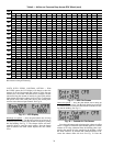
Fig. 19 — Exhaust Air Offset Screen
387.eps
Fig. 20 — Modulating Cfm
a62-388.eps
Fig. 21 — Maximum Cfm Screen
a62-389.eps
Fig. 22 — Minimum CO
2
Screen
a62-390.eps
Fig. 23 — Maximum CO
2
Screen
a62-391.eps