


17
Step 7 — Make Electrical Connections
POWER SUPPLY — The electrical characteristics of the
available power supply must agree with the unit nameplate
rating. Supply voltage must be within the limits shown. See Ta-
bles 3-5 for electrical and configuration data.
ELECTRICAL CONNECTIONS — The ERV unit must
have its own electrical disconnect box. If the disconnect option
has not been ordered from the factory, it must be field supplied
and installed per local codes. See Tables 3-5.
If the ERV unit has an electric pre-heater factory installed, it
will be wired through the ERV unit disconnect.
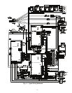
Low Voltage Wiring
— Wire low voltage per Fig. 14. The
field connection terminal strip is located behind the panel that
is adjacent to the control box. The correct panel is marked with
a green label stating “Attention: For field control of ERV, re-
move this panel to gain access to ERV field control terminal
strip.” The wires connecting to the field terminal strip can be
routed through the nearest
3
/
4
-in. hole and through conduit to
the RTU, or they can be routed down the sidewall of the cabi-
net using the wire pull provided and routed through the combi-
nation curb to the RTU.
If the ERV unit is mated to a RTU, terminals C and G on the
field control terminal strip of the ERV unit are connected to the
corresponding terminals on the RTU cabinet. Verify the jumper
is removed from the “ERV R” and “G” terminals; not doing so
may damage RTU control equipment.
When the ERV is to be run as a stand-alone configuration,
verify that a jumper is shorting the “ERV R” and “G” terminals
on the ERV field control terminal strip. This will enable the
ERV to turn on and run.
If the HVAC unit has an integrated economizer or power ex-
haust, it is sometimes necessary to provide an interface be-
tween the HVAC unit and the ERV controls to ensure proper
operation of the ERV’s supply/exhaust fan and energy recovery
wheel motors. The 62E has discrete inputs for this purpose and
damper end switches or relays may be used to coordinate the
economizer and power exhaust operation with the ERV.
When an ERV is mated to an electro-mechanical rooftop
unit with an economizer and a power exhaust, terminals C and
G on the ERV field control terminal strip are still connected to
the corresponding terminals on the rooftop unit cabinet (jumper
across R and G needs to be removed). However, in addition,
field supplied and installed end switches are required to coordi-
nate operation with the unit. For unit economizer operation, it
is necessary to install an Normally Open end switch (field pro-
vided) on the economizer actuator and connect to terminals 5
and 6 (ERV Shutdown) on the ERV terminal strip. This will
cause the ERV to shut down during unit economizer operation.
For power exhaust, based on building pressure control, no ad-
ditional ERV wiring is required, however if the ERV is to pro-
vide power exhaust functionality then a field-installed Normal-
ly Closed end switch is required to be installed between termi-
nals 7 and 8 on the ERV terminal strip.
High Voltage Wiring
— Connect high voltage wiring to the
disconnect, see Fig. 14. Route the power wires in water tight
conduit from the disconnect switch box to the ERV distribution
block. To gain access to high voltage block, remove panel
marked with label stating, “High voltage terminal block locat-
ed behind this panel.”
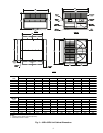
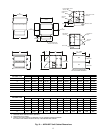
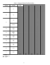
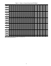
Table 3 — ERV Wheel Motor and Control
Transformer Electrical Data
LEGEND
WARNING
Prior to performing service or maintenance operations on
the ERV unit, turn off and disconnect all power switches to
the unit. Be aware that there may be more than one discon-
nect switch. Electrical shock could cause serious personal
injury or death.
IMPORTANT: Only trained, qualified installers and ser-
vice technicians should install, wire, start-up and service
equipment.
CAUTION
When routing wires in the ERV always keep them away
from moving parts and sharp metal edges. Follow all local
and state codes when routing the ERV control wires.
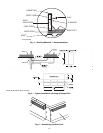
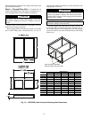
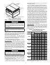
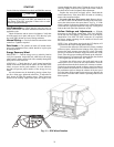
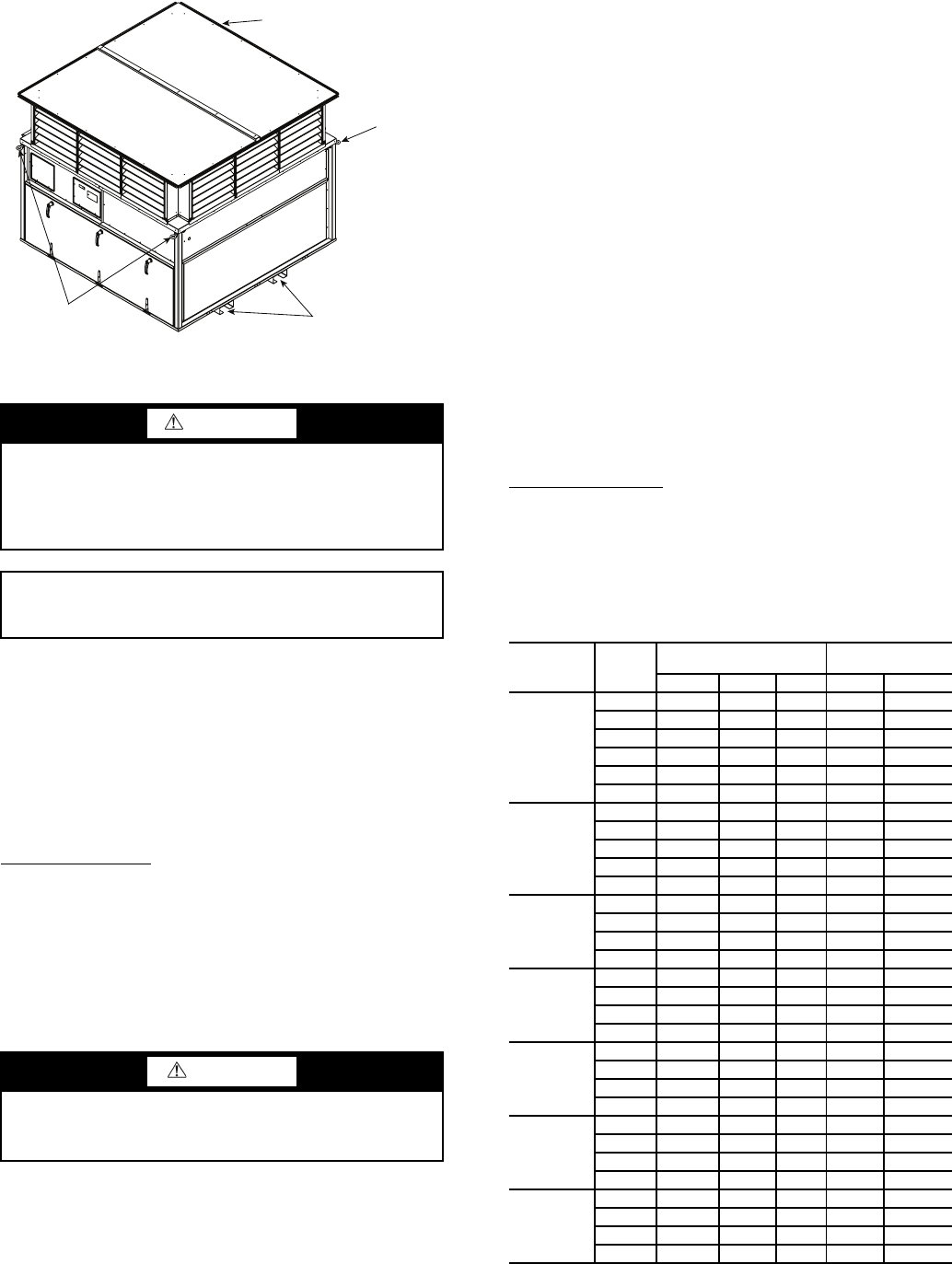
Fig. 13 — Rigging and Handling
FORK POCKETS
EYE HOOK
(HIDDEN)
EYE HOOK
EYE HOOKS
a62-380
UNIT
UNIT
V-Ph
ERV WHEEL MOTOR
CONTROL
TRANSFORMER
V-Ph W FLA V FLA
62EB,E7
115-1 115-1 80.5 0.70 75 0.65
230-1 230-1 69.0 0.30 75 0.33
230-3 230-1 69.0 0.30 75 0.33
400-3 230-1 69.0 0.15 75 0.16
460-3 230-1 69.0 0.15 75 0.16
575-3 230-1 69.0 0.12 75 0.13
62EC,E2
230-1 230-1 69.0 0.30 75 0.33
230-3 230-1 69.0 0.30 75 0.33
400-3 230-1 69.0 0.15 75 0.16
460-3 230-1 69.0 0.15 75 0.16
575-3 230-1 69.0 0.12 75 0.13
62ED,E3
230-3 230-1 69.0 0.30 75 0.33
400-3 230-1 69.0 0.15 75 0.16
460-3 230-1 69.0 0.15 75 0.16
575-3 230-1 69.0 0.12 75 0.13
62EE,E4
230-3 230-3 138.3 1.04 75 0.33
400-3 460-3 138.3 0.52 75 0.16
460-3 460-3 138.3 0.52 75 0.16
575-3 575-3 99.7 0.30 75 0.13
62EH,E5
230-3 230-3 99.7 0.75 75 0.33
400-3 460-3 101.0 0.38 75 0.16
460-3 460-3 101.0 0.38 75 0.16
575-3 575-3 99.7 0.30 75 0.13
62EK,EL,EM,
EN,EP,E6
230-3 230-3 332.4 2.50 75 0.33
400-3 460-3 319.1 1.20 75 0.16
460-3 460-3 319.1 1.20 75 0.16
575-3 575-3 315.8 0.95 75 0.13
62ER,ES,
ET,EU
230-3 230-3 452.0 3.40 75 0.33
400-3 460-3 452.0 1.70 75 0.16
460-3 460-3 452.0 1.70 75 0.16
575-3 575-3 465.3 1.40 75 0.13
FLA — Full Load Amps W—Watts