


32
SENSOR ENABLE (BV:12) is set to 0, then the ERV will use
the DCV CO2 INSIDE (AV:2) parameter. Any value can be
written into this parameter.
The ERV will look at this parameter along with parameters:
REMOTE MIN DCV VALUE SETPOINT (AV:17), RE-
MOTE MAX DCV VALUE SETPOINT (AV:15), REMOTE
MIN CFM SETPOINT (AV:16), and REMOTE MAX CFM
SETPOINT (AV:14) to determine the settings for the ERV.
These 4 remote set points will only be used if the REMOTE
AIRFLOW CONFIGURATION MODE (AV:10) parameter is
not 0. Otherwise the values that have been loaded locally into
the ERV will be used.
EX FILTER BP (AV:22) AND OA FILTER BP (AV:23)
—
These status points show the pressure drop across each air fil-
ter. This pressure drop is used to determine when the air filters
are dirty. These numbers will always be 0 unless the ERV was
ordered with this option.
REMOTE EX FILTER BP SETPOINT (AV:24) AND
REMOTE OA FILTER BP SETPOINT (AV:25) — These
set points are related to the dirty filter indicator option of the
ERV. If the ERV has the dirty filter indicator option installed
this parameter will set the trip point for which the ERV will
give a dirty filter alarm. This number will be dependent on the
airflow that the ERV is set to. The best way to determine the
dirty filter set points is to use the unit status parameters called
EX FILTER BP (AV:22) and OA FILTER BP (AV:23). With
clean filters in the ERV, and the ERV running at its design con-
ditions, note the values of the filter status parameters. Multiply
those numbers by 1.5 and use them for the filter set points.
These set points will overwrite the value that was set locally
into the ERV. If this value is changed locally it will overwrite
the value that was set remotely.
REMOTE EX FAN SPEED SETPOINT (AV:27) AND
REMOTE OA FAN SPEED SETPOINT (AV:28) — These
parameters allow for direct input to tell the fans how fast to run.
The parameter needs to be set to a number between 1% and
100%. When this parameter is set to 0% the ERV’s internal
control board will take control of the fans.
ERV WHEEL SPEED (AV:29)
— This status shows the
speed that the ERV heat exchanger wheel is running on a scale
of 0 to 100%. If the ERV was not ordered with a variable fre-
quency drive on the wheel this status will always read 100%.
REMOTE VFD WHEEL SPEED SETPOINT (AV:30)
—
This parameter allows for the wheel rotation speed to be varied.
This is often used to change the efficiency of the Energy Re-
covery Heat Exchanger Wheel to maintain a constant discharge
temperature. This needs to be entered as a number that is be-
tween 1% and 100%. Entering 0% will put the wheel speed in
automatic mode, and the ERV control board will take control.
To turn off the wheel use the REMOTE WHEEL BYPASS
ENABLE (BV:16) parameter.
ERV 2POS DAMPER STAT (BV:l)
— This status shows if
the ERV is commanding the two-position dampers to open.
This status will update whether the ERV was ordered with two-
position dampers or not.
ERV EX STAT (BV:2) AND ERV OA STAT (BV:3)
—
These status points output a logic 1 to show when the fan is
ON.
ERV WHEEL STAT (BV:4)
— The ERV WHEEL STAT sta-
tus shows whether or not the ERV heat exchange wheel is
running.
ERV EX BLOWER ALARM (BV:5) AND ERV OA
BLOWER ALARM (BV:8) — These alarms indicate a cata-
strophic failure of a blower in the ERV. The alarms can also in-
dicate a missing leg of incoming power, over voltage, under
voltage or extremely dirty incoming power to the ERV. These
alarms will never go active if the ERV was not ordered with the
blower alarm options.
FIX WHEEL ALARM (BV:7)
— This alarm indicates that
the ERV heat exchange wheel is not turning when it is sup-
posed to be turning. This alarm will never go active if the ERV
was not ordered with this alarm option.
EX DIRTY FILTER ALARM (BV:6) AND OA DIRTY
FILTER ALARM (BV:9) — This alarm indicates that the air
filters in the ERV need to be changed. These alarms are related
to parameters REMOTE EX FILTER BP SETPOINT (AV:24)
and REMOTE OA FILTER BP SETPOINT (AV:25). The set
points determine when the ERV is going to give a dirty filter
alarm. This alarm will never go active if the ERV was not or-
dered with the dirty filter alarm options.
OA LOW CFM (BV:10)
— This alarm becomes active if the
desired outside air CFM set point is not being met. The alarm
will only trip if the desired outside air CFM set point has not
been satisfied for 5 minutes.
REMOTE BP SENSOR ENABLE (BV:11)
— If this param-
eter is set to OFF the ERV will use the building pressure read-
ing off of the sensor inside the ERV. If the parameter is set to
ON, the ERV will use the building pressure value that is being
written in parameter REMOTE BP SENSOR VALUE.
REMOTE ERV DOWN ENABLE (BV:13)
— This parame-
ter is another start/stop command for the ERV. Turning this pa-
rameter to 1 will shut the ERV down. Unlike the REMOTE
START STOP (BV:15) parameter, it is not dependant on the
REMOTE AIRFLOW CONFIGURATION MODE (AV:10)
parameter.
REMOTE PWR EXHAUST ENABLE (BV:14)
— This pa-
rameter puts the ERV into a power exhaust mode that is usually
used in conjunction with the economizer of the rooftop unit.
The power exhaust mode turns off the wheel and the outside air
blower. The exhaust blower will continue to run at its current
set point. Setting this parameter to 1 will put the ERV into pow-
er exhaust mode.
REMOTE START STOP (BV:15)
— This parameter allows
the user to turn on/off the ERV. Setting this parameter to 1 will
turn the ERV ON. The REMOTE START STOP works in con-
junction with the start/stop contact on the ERV field terminal
strip if the REMOTE AIRFLOW CONFIGURATION MODE
(AV:10) is set to 0. If the REMOTE AIRFLOW CONFIGU-
RATION MODE (AV:10) is not set to 0, then the REMOTE
START STOP parameter will override the field terminal strip.
REMOTE WHEEL BYPASS ENABLE (BV:16)
— Setting
this parameter to 1 will turn off the ERV heat exchange wheel.
This mode is normally used to disable the wheel when free
cooling is available.
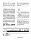
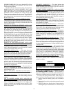
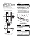
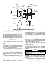
SERVICE
Removing and Installing Non-Segmented Wheel
for Cleaning (62EB,E7 Units) —
Non-segmented en-
ergy transfer wheels are secured to the shaft and bearing sup-
port beam by a Phillips head screw and hub cover. See Fig. 30.
To remove the energy transfer wheel, follow Steps 1-4
below. (See Fig. 30.) Reverse procedure for wheel installation.
1. Remove front seal assembly (pulley side of cassette) if
present.
2. Remove belt from pulley and position temporarily around
wheel rim.
3. Remove the hub cover from the wheel. Note the wheel to
shaft alignment pin under the hub cover. Ensure this pin
CAUTION
Disconnect electrical power before servicing energy recov-
ery cassette. Failure to do so could result in personal injury.