


34
NOTE: The 62EBA, 62EBC, 62ECC, 62E7A, 62E7C, and
62E2C units contain non-segmented wheels which must be
completely removed to be cleaned.
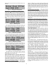
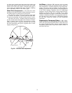
1. Begin by positioning one segment opening at the top of
the cassette. Unlock and open the segment retaining
brackets on both sides of the selected segment opening.
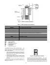
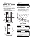
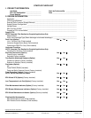
2. Holding the segment as vertical as possible and
centered between spokes, insert nose of segment down-
ward between the hub plates. See Fig. 34.
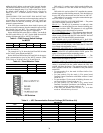
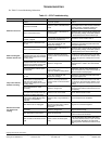
NOTE: The face of the segment, with the imbedded
stiffener (vertical support between nose and rim end of
segment) must face the motor side of the cassette. See
Fig. 35.
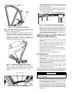
3. Ease the segment downward until its outer rim clears the
inside of the wheel rim. Then press the segment inward
against the spoke flanges.
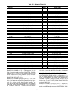
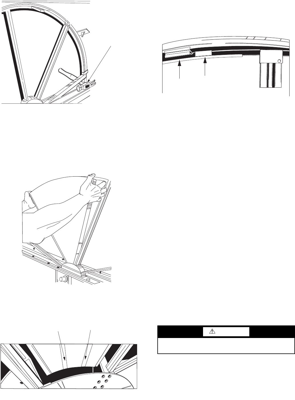
4. Close and latch segment retaining brackets to the position
shown in Fig. 36. Make certain the retaining bracket is
fully engaged under the catch.
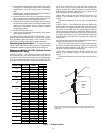
5. Slowly rotate, by hand, the first installed segment to the
bottom of the cassette, then install the second segment
opposite the first. Repeat this sequence with the 2 in-
stalled segments rotated to the horizontal position to bal-
ance the weight of installed segments. Continue this se-
quence with the remaining segments.
Wheel Drive Motor and Pulley Replacement
(62EC-EU and 62E2-E6 Units)
1. Disconnect power to wheel drive motor.
2. Remove belt from pulley and position temporarily around
wheel rim.
3. Loosen setscrew in wheel drive pulley using Allen
wrench and remove pulley from motor drive shaft.
4. While supporting weight of drive motor in one hand,
loosen and remove 4 mounting bolts.
5. Install replacement motor with hardware kit supplied.
6. Install pulley to dimension shown in Fig. 37 and secure
setscrew to drive shaft.
7. Stretch belt over pulley and engage in groove.
Belt Replacement
1. Obtain access to the pulley side bearing access plate.
Remove 2 bearing access plate retaining screws and the
access plate.
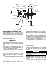
2. Using hexagonal wrench, loosen setscrew in bearing
locking collar. Using light hammer and drift (in drift pin
hole) tap collar in the direction of wheel rotation to
unlock collar. Remove collar.
3. Using socket wrench with extension, remove 2 nuts
which secure bearing housing to the bearing support
beam. Slide bearing from shaft.
NOTE: Slight hand pressure against wheel rim will lift weight
of wheel from inner race of bearing to assist bearing removal
and installation. If not removable by hand, use bearing puller.
4. Using a wrench, remove diameter seal retaining screws or
hub seal retaining screws. Remove diameter seals or hub
seal from bearing beam. See Fig. 38.
5. Form a small loop of belt and pass it through the hole in
the bearing support beam. Grasp the belt at the wheel hub
and pull the entire belt down. Loop the trailing end of the
belt over the shaft (Fig. 38 shows belt partially through
the opening).
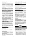
HAMMER
USED AS
“STOP”
Fig. 33 — Using a Stop on the Wheel
A62-280ef
Fig. 34 — Inserting a Segment of the Wheel
A62-281ef
Imbedded Stiffeners
Fig. 35 — Motor Side View of Segment
A62-282ef
CAUTION
Protect hands and belt from possible sharp edges of hole in
bearing support beam.
CATCH
PULL TAB
Fig. 36 — Latch Segment Retaining Brackets
A62-283ef