


11
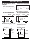
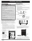
1. Determine the location of the range center line and front
panel for the range’s final position based on the Product
Dimensions on page 5 and the actual cabinet/cutout
dimensions used for the installation.
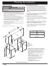
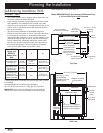
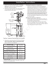
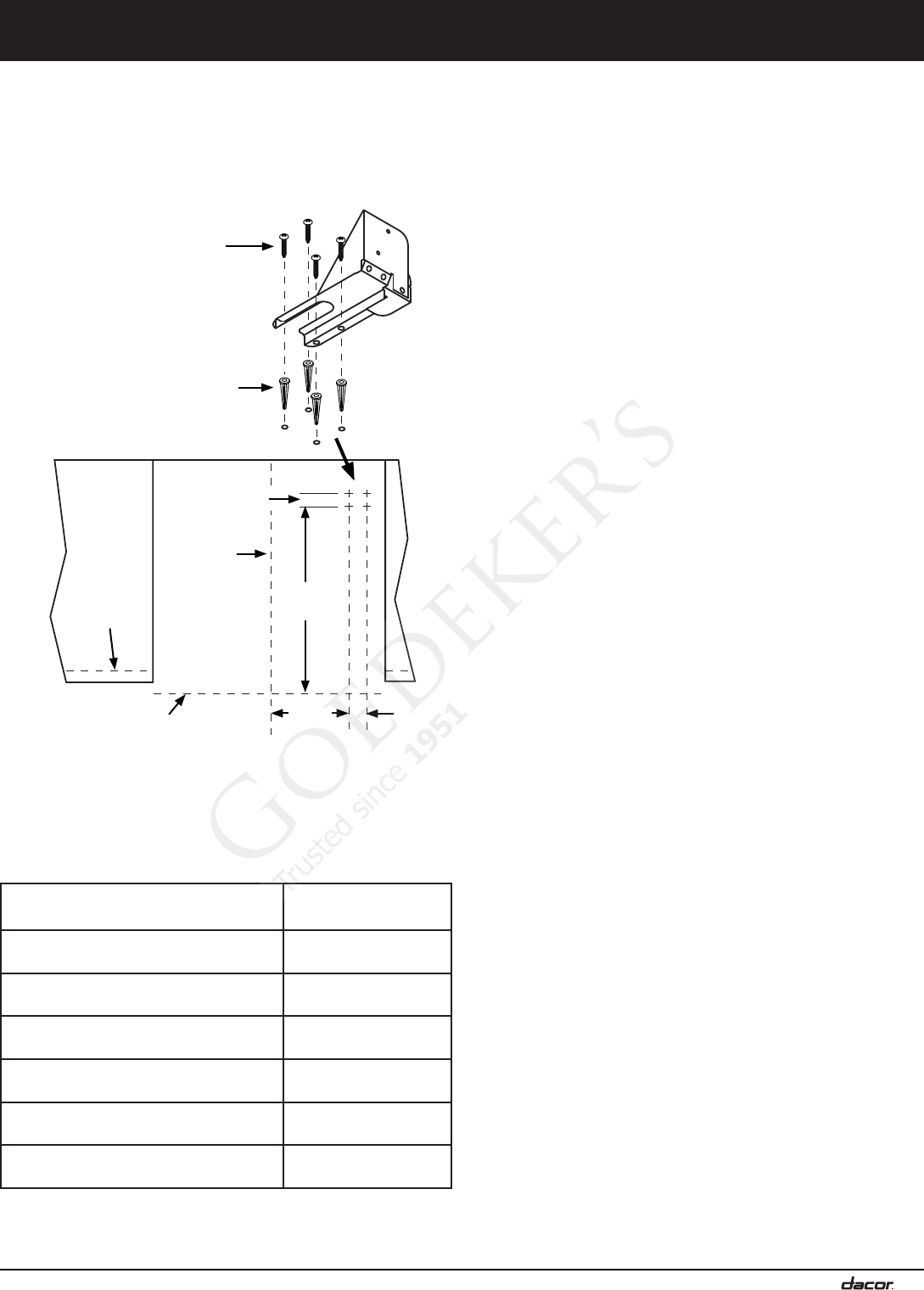
2. Determine the required position of the anti-tip bracket, based
on the diagram below. Mark the four (4) mounting hole
locations on the floor with a pencil.
3. Determine the screw size required. The minimum full thread
depth (portion of screw threaded into wood/slab) for wood
is 3/8” (1 cm) and 5/8” (1.6 cm) for concrete. See the table
below to select the correct screw size.
Sub-Floor Type/
Floor Covering Thickness
Screw Size
Concrete or wood sub-floor, no floor
covering over top
#8 x 1 *
Concrete or wood sub-floor, floor
covering up to 1/4” thick
#8 x 1 *
Concrete or wood sub-floor, floor
covering over 1/4” and up to 1/2” thick
#8 x 1 1/4 *
Wood sub-floor, floor covering over
1/2” and up to 1 3/16” thick
#12 x 1 3/4 *
Concrete under floor covering
over 1/2” thick
Must be purchased
separately **
Wood sub-floor, floor covering
over 1 3/16” thick
Must be purchased
separately **
* Included with range
** Determine required depth based on information in step 3 and
purchase from local hardware store.
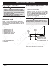
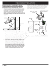
Attaching the bracket to a concrete floor:
• Drill four (4) 3/8” diameter countersink holes through any
existing floor covering down to the concrete slab below.
• Drill the 4 holes for the anchors 1 1/4” (3.2 cm) deep into the
concrete slab using a 3/16” masonry bit. This hole length is
longer than the anchor, but is required for proper installation.
Clear the holes of dust and any other material. Tap each
anchor into the hole until the anchor top is flush with the top
of the concrete slab. Position the anti-tip bracket holes over
the anchor holes. Insert the screws through the 4 holes in
the base of the bracket and thread them into the anchors. Be
sure the screw threads fully engage the anchor body. Tighten
the screws into place.
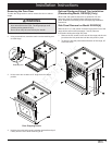
Attaching the bracket to a wood floor:
• If there is ceramic, asphalt or other hard floor covering over
the wood below, drill (4) countersink holes to allow access to
the wood below for drilling pilot holes.
• Drill four (4) pilot holes into the wood floor using a drill bit
(1/16” dia. for #8 screws, 1/8” dia. for #12 screws). Position
the anti-tip bracket holes over the holes in the floor. Insert the
screws into the wood and tighten into place.
Installation Instructions
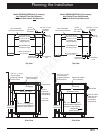
C
L
#8 x 1”
#8 x 1 1/4” or
#12 x 1 3/4
screw,
4 places
(see text)
Range front
panel
Range
center line
1 1/2” (3.8 cm)
2 3/16”
(5.6 cm)
21 1/4”
(54.0 cm)
9 7/8”
(25.1 cm)
Anchor, 4 places:
use for concrete
floor only
Cabinet
face below
countertop
Top View - Location of Floor Mounted Anti-Tip Bracket