


4
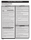
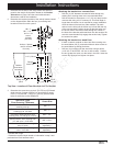
Planning the Installation
B
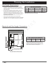
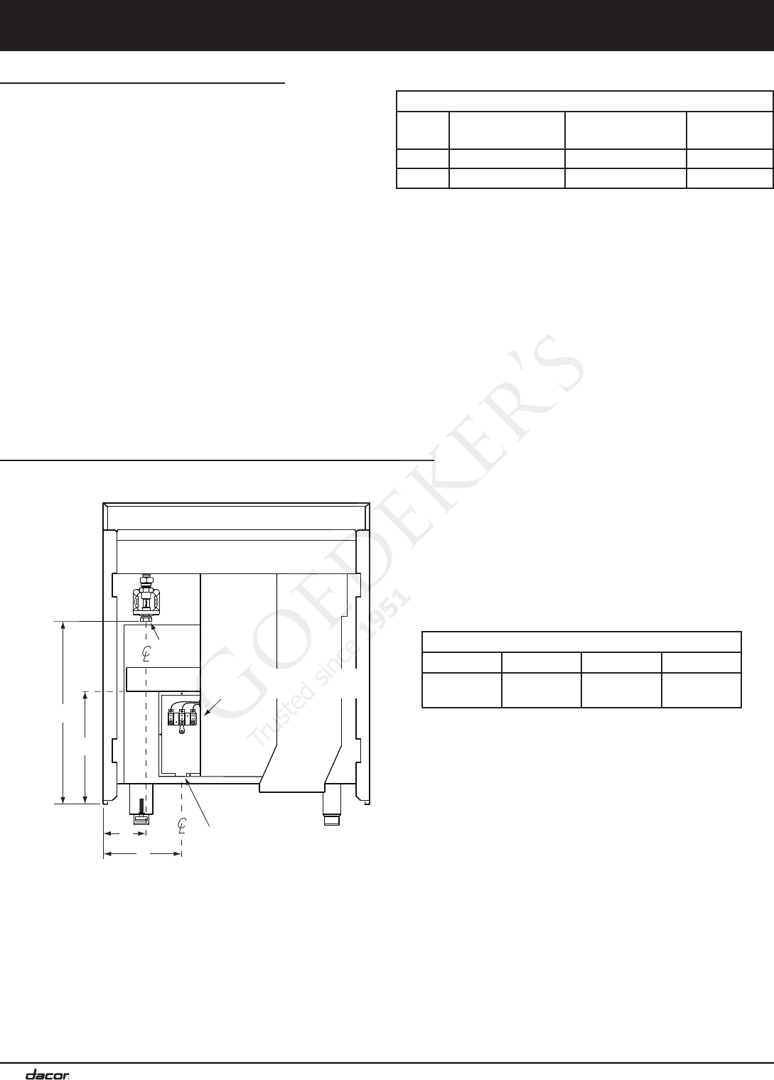
Gas
inlet
A
C
7/8” (2.2 cm) dia. electrical
connection hole in bottom*
D
Range electrical access,
cover removed
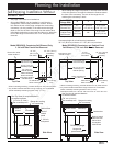
Gas and Electrical Dimensions
Gas - Electrical Access Dimensions
A B C D
4 3/4”
(12.1 cm)
22 1/8”
(56.2 cm)
8 3/4”
(22.2 cm)
13 3/4”
(34.9 cm)
* When using an appliance cord that is not factory
installed, the hole size must be increased to 1 1/8”
(2.9 cm) by removing the conduit bracket inside the
range electrical access box (see page 14).
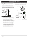
Gas Supply Requirements
• Check your local building codes for the proper method of
installation. In the absence of local codes, this appliance
should be installed in accordance with the National Fuel Gas
Code ANSI Z223.1.
• Be certain that the appliance being installed is correct for
the gas service provided (natural gas or LP gas). Also, if
operating the range at an altitude above 4000 ft. (1219 m)
make sure it is equipped for high altitude operation. Refer to
the product data label and the table on the inside cover to
determine the correct model.
• See the table for gas supply pressure requirements.
• The regulator inlet accommodates a 3/4” gas line. The range
ships with a 1/2” to 3/4” adapter connected to the regulator.
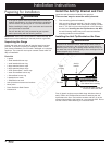
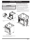
Electrical and Gas Supply Connections
Gas Supply Specifications
Gas
Type
Manifold
Pressure* (WC)
Min. Gas Supply
Pressure (WC)
Max. Input
Pressure
Natural 5 6 1/2 psi
LP 10 11 1/2 psi
The ratings above are for reference only - refer to the product
data label (see inside cover for location).