


18
Installation Instructions
Final Installation
1. Peel the protective plastic coating off of the range, including
the range door.
2. Measure from the floor to the countertop.
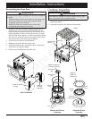
3. Adjust the leveling legs:
On freestanding units, adjust the leveling legs as required
to position the trim around the edge of the cooktop even with
or above the countertop.
On self-rimming units, adjust the leveling legs to position
the bottom edge of the range top trim slightly above
countertop height.
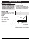
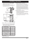
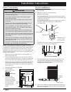
4. Locate the anti-tip foot on the back of the range and lower
(turn) it until it is 1/16” (2 mm) off the floor.
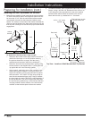
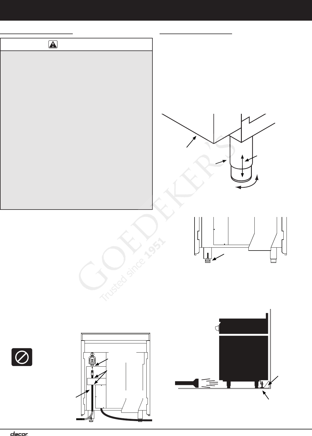
5. Carefully slide the range into position into the cutout. The
anti-tip foot should engage the anti-tip bracket. Using a
flashlight look underneath the range and verify that the
bracket covers the anti-tip foot.
6. Use a level to make sure that the range does not tilt front to
back or side to side. Re-adjust the legs to level and change
the height if necessary.
Anti-Tip Foot Location
Anti-tip
foot
Back of
range
up
down
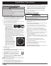
Back of range
2 1/8” *
* Distance to floor:
2 7/8” (7.3 cm)
to 5” (12.7 cm)
Rear leg
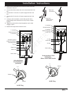
Gas Connection
WARNING
• Make sure the gas supply valve is off and that the power to
the range is turned off at the circuit breaker or fuse box prior
to connecting the gas line.
• Do not apply excessive pressure when tightening gas
connections and fittings.
• Do not use Teflon tape or plumber’s putty on gas flex line
connections.
• Check for gas leaks as instructed below before using the
appliance. Do not use a flame to check for leaks.
• For LP installations, the LP gas tank must have its own
high pressure regulator. This is in addition to the pressure
regulator provided with the range.
• The maximum gas supply pressure to the regulator must
never exceed 1/2 pound per square inch (psi) or 3.5 kPa.
• The range and shut-off valve must be disconnected from the
gas supply piping during any pressure testing exceeding 1/2
psi (3.5 kPa).
• The range must be isolated from the gas supply piping by
closing the shut-off valve during any pressure testing at or
below 1/2 psi (3.5 kPa).
• Be careful not to damage the wires inside the chassis while
pushing the gas line through the access holes.
NOTE: The gas pressure regulator is pre-set at the factory for
the type of gas intended for use with the appliance. To verify that
the appliance is compatible with the type of gas available, check
the product data label (see inside cover for location). Ranges
intended for use with LP gas will have “LP” as a part of the model
number. Consult your dealer if the range is not compatible with
the type of gas supplied.
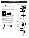
1. Make sure the gas supply valve is in the off position and
power to the range is off.
2. Connect a flexible gas supply line to the gas shut-off valve
previously installed on the stub out. The gas line needs to be
long enough to allow the range to be pulled out for service.
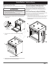
3. Slide the gas line up through the access holes in the chassis
and up to the regulator. Move the wires around inside the
access holes to prevent them from catching on the gas line
as you push it up.
4. Connect the gas line to the regulator.
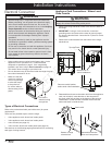
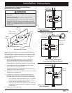
5. Turn all cooktop
control valves to the
OFF position.
6. Turn on the gas
supply and check all
lines and connections
for leaks using a soap
and water solution.
7. Turn the gas shut-
off valve to the off
position.
OFF Icon
Gas
line
Regulator
connection
Access
holes
Back of range
Anti-tip
bracket
Anti-tip foot