


57
3 Operation
The safety instructions in Section 2, "Safety" must have been read
and understood before operating the dispensing station.
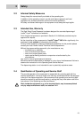
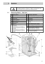
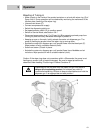
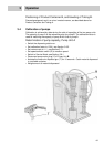
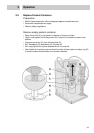
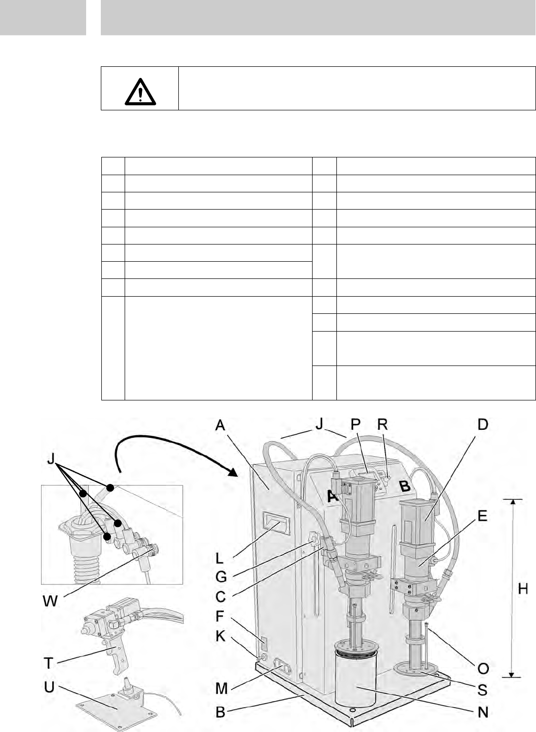
3.1 Dispensing Station – Total View
A
Control cabinet
K
Connector, pneumatics
B
Base plate
L
Carrying handle
C
Pressure switch
M
Power switch, Fuse plug, Socket
D
Pump motor
N
Receptacle
E
Planetary gearbox
O
Vent screw
F
Type plate
G
Locking screw
P
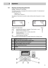
Electronic pump controller with
display
H
Pump unit
R
Speed selector switch (output)
S
Follower plate with wiper ring
T
Meter-mix Dispense Applicator
U
Docking station for meter-mix
dispense applicator (optional)
J
Tubing set consists of:
– Feedlines,
– Compressed air hose
meter-mix
dispense applicator
0 (applicator
closed)
– Compressed air hose
meter-mix
dispense applicator I (applicator
open)
W
Connector, docking station for meter-
mix dispense applicator