


88
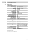
8 Technical Specification
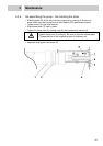
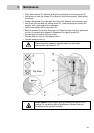
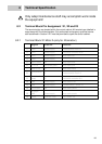
Only adept maintenance staff may accomplish work inside
the equipment!
8.2 Terminal Block Pin Assignment X1, X2 and X3
The terminal strips are located within the control cabinet. All terminals are labelled in
accordance with the following table. Only authorised and properly qualified service
staff as defined in Section 2.4.2 must be permitted to open the control cabinet.
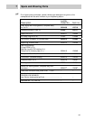
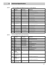
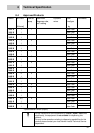
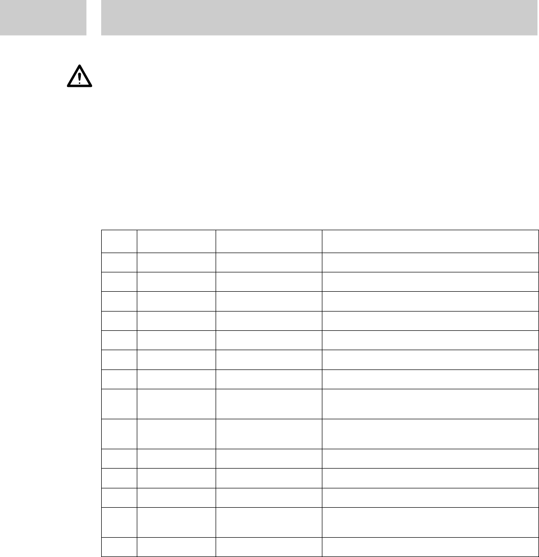
8.2.1 Terminal Block X1 Motor A (only for Information)
Signal internal external
1
+24V Power supply Pressure switch Part A 1
2
+24V Power supply Limit switch container A sw
3
+24V Power supply Motor cable red
4
+24V Power supply
5
Right rotation Q1 Motor cable blue
6
0-10 Volt Pot centre green Motor cable pink
7
Motor A OK I3 Motor cable white
8
Overpressure
A I1 Pressure switch Part A 2
9
Container A
empty I5 Limit switch container A rt
10
GND Power supply Motor cable A sw
11
GND Power supply Pot GND white + shield / Z1
12
Left rotation Q2 Motor cable yellow
13
Analogue
GND Power supply Motor cable purple
14
+8Volt Stabiliser 7808 Pot + brown / Z2