


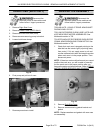
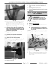
Fig. 110
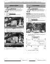
10. Apply power to oven and carefully jog motor to
place crank pointing toward side with interior
light. Ensure crank arm is parallel with oven wall.
Position motor as necessary while maintaining
adjustment in previous step.
11. Jog motor to point crank arm to opposite side of
oven. Ensure crank arm is parallel with oven wall.
Position motor as necessary while maintaining
adjustment in previous steps.
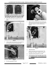
12. Repeat steps 6 thru 11 as necessary until
conditions are met.
13. Jog motor to put crank arm pointing down.
14. Disconnect power to oven.
15. Tighten gear case mounting screws.
NOTE: Non-drive end rotor shaft should seat itself in
lower notch of support bearing. This is normal
operating position.
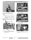
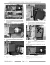
Fig. 111
16. Lift rotor out of oven.
17. Check for proper removal and installation of
rotor.
18. Tighten gasket bracket screws.
19. Continue reassembly and check oven for proper
operation.
DRIVE MOTOR, SPEED REDUCER
AND GEARBOX
Disconnect the
electrical power to the machine and
follow lockout / tagout procedures.
1. Remove the rotor.
2. Remove
Right Side Cover.
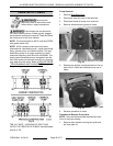
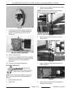
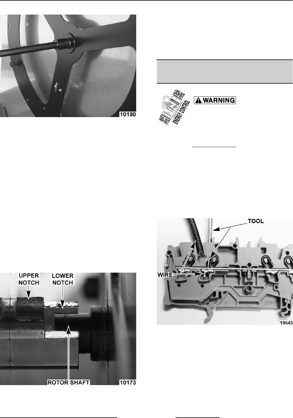
3. Identify and remove motor wires from terminal
block.
A. Insert jeweler screwdriver or similar small
tool into holes to release spring tension and
pull wires out.
NOTE: The following picture shows the terminal block
disassembled to illustrate how the tool is inserted to
release the wire.
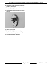
Fig. 112
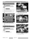
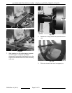
4. Remove four screws securing pump mounting
box and allow box to slide down for access to
motor screws.
KA SERIES ELECTRIC ROTARY OVENS - REMOVAL AND REPLACEMENT OF PARTS
Page 33 of 72 F25294 Rev. A (0412)