


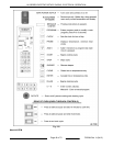
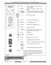

K ...................... TB2 power in terminal block
L ...................... Drive motor assembly M3
M ..................... Utility plate (for grease assist option)
N ...................... Electrical Connection (E1)
O ...................... Grease Assist, Pumped Drain (P2)
P ...................... Drain (main & sump) (P1)
Q ...................... TB3 terminal strip located above and behind pump.
R ...................... Grease Pump - Models with grease assist only.
S ...................... Sump Drain Level, Manual
1 ...................... Keypad and display board assembly
2 ...................... Rotate switches
3 ...................... Power switch
4 ...................... Meat probe mini jack
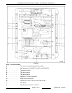
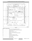
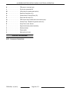
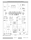
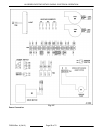
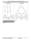
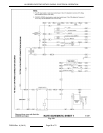
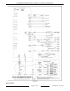
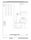
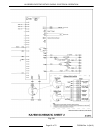
WIRING DIAGRAMS
KA7E - Component Connections
KA SERIES ELECTRIC ROTARY OVENS - ELECTRICAL OPERATION
F25294 Rev. A (0412) Page 54 of 72