


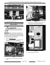
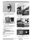
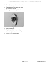
Fig. 101
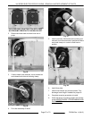
9. If replacing any individual piece, remove four
screws securing motor and speed reducer to
gearbox. Torque screws to 22 inch lbs. on
reassembly.
MOTOR ALREADY REMOVED
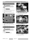
10. Install in reverse order.
11. Snug but do not tighten screws securing gasket
bracket at this time. Bracket and gasket must be
loose during the drive motor adjustment
procedure.
12. Continue to Drive Motor Adjustment.
Drive Motor Adjustment
Disconnect the
electrical power to the machine and
follow lockout / tagout procedures.
NOTE: Some pictures show different model oven
parts. They are used for view and adjustment is
identical.
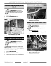
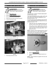
1. Remove Right Side Cover.
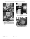
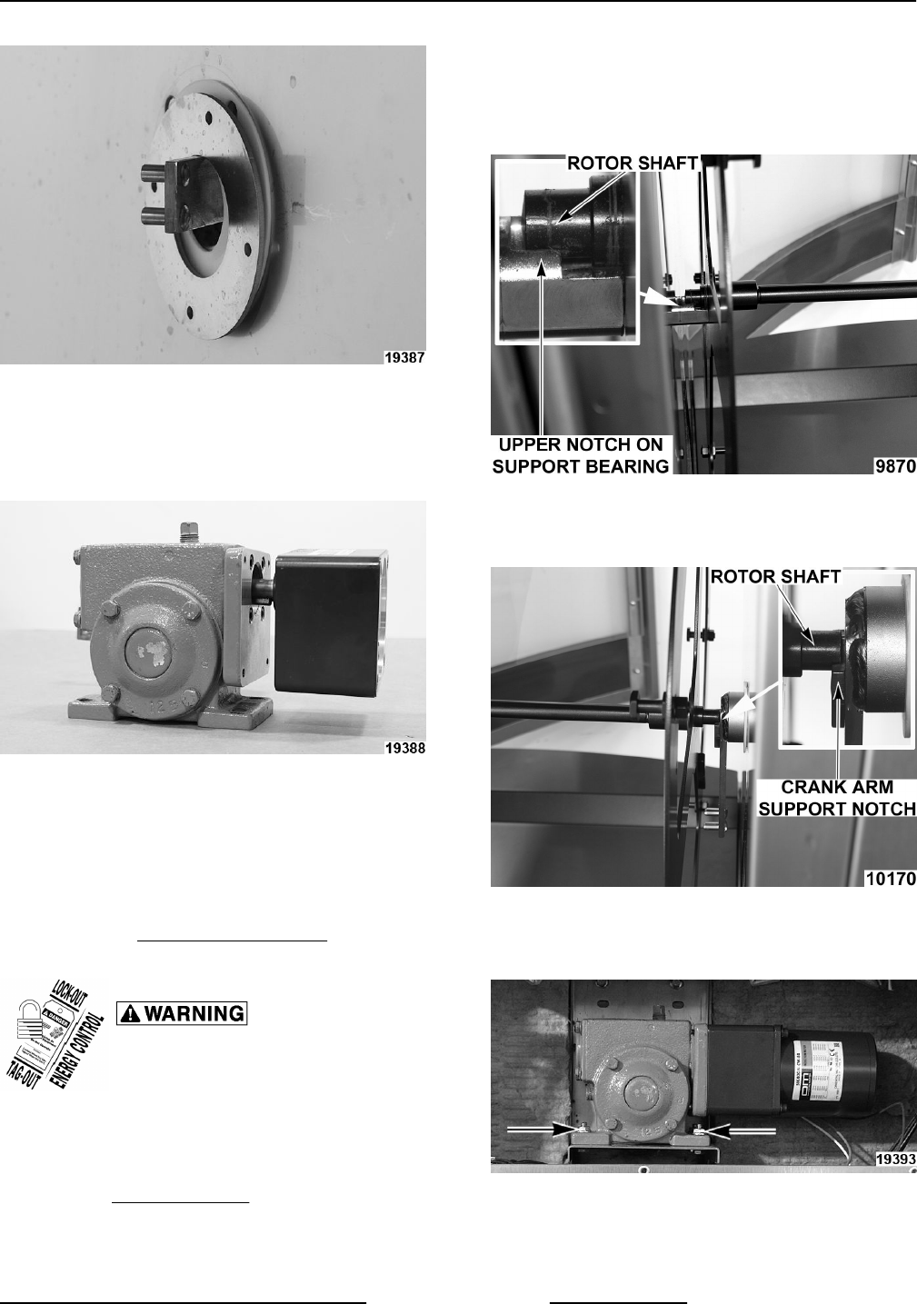
2. Install rotor.
3. Place non-driven side of rotor shaft onto upper
notch of support bearing.
NOTE: Ensure rotor is slid as far as possible on
bearing support toward non-drive side.
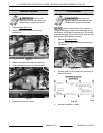
Fig. 103
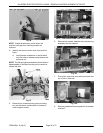
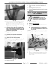
4. Place drive end of rotor shaft on crank arm
support notch.
Fig. 104
5. Loosen screws securing rotor drive motor to
support bracket.
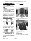
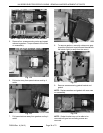
Fig. 105
6. Use a square or similar tool to make gearbox
square to motor support.
KA SERIES ELECTRIC ROTARY OVENS - REMOVAL AND REPLACEMENT OF PARTS
Page 31 of 72 F25294 Rev. A (0412)