


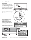
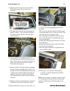
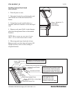
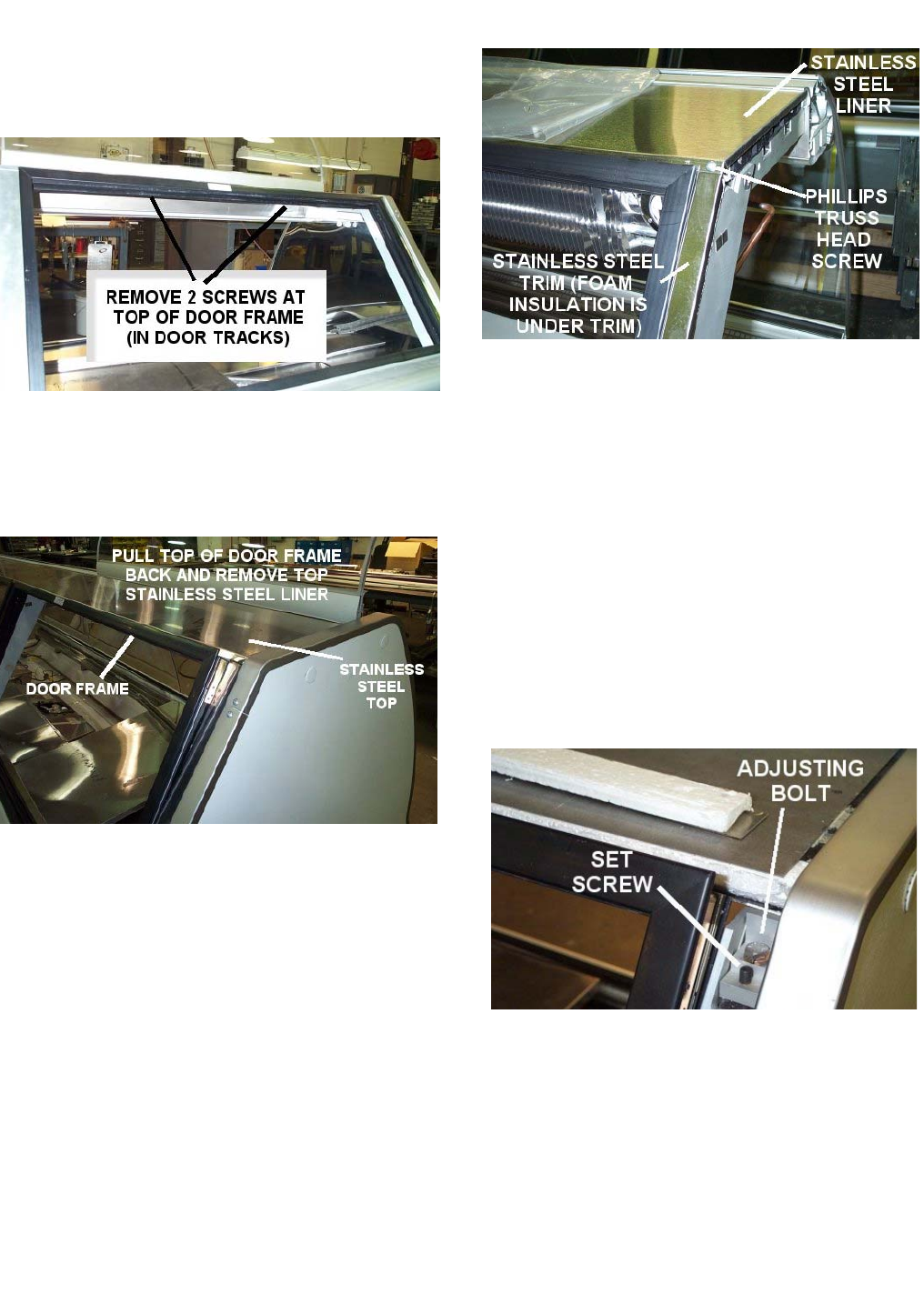
4. Remove screws at top of rear door frame.
The bottom screws do not need to be
removed.
5. Pull back the top of the door frame approxi-
mately 2 inches. This will allow clearance
for removal of the stainless steel top liner
and trim pieces.
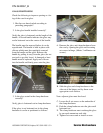
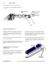
6. Some models have a Phillips truss head
screw holding the stainless steel liner to the
trim. These screws are visible from the rear
of the case to the side of the door frame.
These must be removed.
7. Remove stainless steel top liner by grabbing
the rear flange and pulling back. Note: It is
possible to access the adjusting bolt by using
a small swivel socket without removing the
stainless top liner. To do this, the stainless
steel trim and foam noted in Step 8 must be
removed.
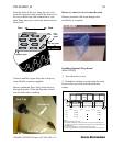
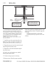
8. Remove stainless steel trim pieces and foam
insulation on each side of the door frame.
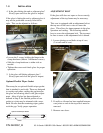
9. The set screw and adjusting bolt are now
accessible.
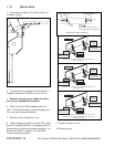
• The set screw must be backed out before turn-
ing the adjusting bolt, (
1
/
8 inch set screw). The
set screw serves as a positive stop.
• The adjusting bolt should be turned no more
than a half-turn before inspecting glass posi-
tion and operation.
• Turning the adjusting bolt clockwise will raise
the front glass.
• Turning the adjusting bolt counter-clockwise
will lower the front glass.
• Once the glass position is set, tighten the set
screw (positive stop).
10. Once glass is positioned and operating
correctly, re-install components and hard-
ware removed.
Note: the door frame is designed to have a tight
fit. A putty knife between the top of the frame
and the insulated panel will help guide it into
position.
P/N 0420057_B 1-7
Service Merchandisers
HUSSMANN CORPORATION, Bridgeton, MO 63044-2483 U.S.A.