


9
312027000
INSTALLATION
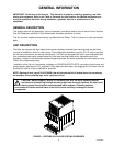
This section covers unpacking and inspection, selecting location, installing the Unit, preparing the Unit for op-
eration, and Unit operation.
UNPACKING AND INSPECTION
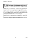
NOTE: The Unit was thoroughly inspected before leaving the factory and the carrier has accepted and
signed for it. Any damage or irregularities should be noted at the time of delivery (or not later than 15
days from date of delivery) and immediately reported to the delivering carrier. Request a written inspec-
tion report from Claims Inspector to substantiate any necessary claim. File claim with the delivering
carrier, not with IMI Cornelius Inc.
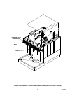
1. After the Unit has been unpacked, remove shipping tape and other packing material.
2. Lift hood straight up and off the Unit.
3. Remove four shipping hex nuts that secure the drop-in refrigeration assembly in the Unit.
4. Unpack LOOSE-SHIPPED PARTS. Make sure all items are present and in good condition.
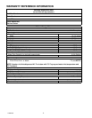
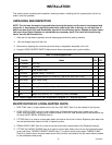
Table 2. Loose-Shipped Parts
Item
No. Part No. Name 5-FL 6-FL
1 317659039 Drip Tray 1 1
2 317660000 Cup Rest 1 1
3 3573 Rear access Panel 1 1
4 17619300 Adaptor Fitting, 7/16-20 (2) -- 1
5 187254000 Sheet Metal Screw, Phil Truss Hd; Type A, No. 6 by 3/8-in. Long 2 2
6 318516000 Drain Hose Clamp 1 1
7 311304000 Tapered Gasket, Black 2 2
8 309852000 Tubing Clamp, .669 I.D. Open .571 I.D. Closed 2 2
9 77040900 Fitting, 90° Swivel Elbow 1 1
10 3297 Water Only Lever Kit, UF-1 Dispensing Valve (see Note) -- 1
NOTE: Loose-shipped with Six-Flavor Dispensers equipped UF-1 dispensing valves.
IDENTIFICATION OF LOOSE-SHIPPED PARTS
1. DRIP TRAY (item 1) to be installed on the Unit, then CUP REST (item 2) to be installed in the drip tray.
2. REAR ACCESS PANEL (item 3) to be installed over Unit base back access hole if power cord, drain
hoses, and inlet supply lines will not be routed out back of the Unit. Rear access panel to be secured to the
Unit with SHEET METAL SCREWS (item 5).
3. FITTING (item 4) is used to connect plain water inlet source line to the six-flavor Dispenser plain water inlet
line that provides plain water to the No. 3 dispensing valve.
4. DRAIN HOSE CLAMP (item 6) is used to connect drain hose (not provided) to the Dispenser drip tray.
5. FITTING, 90° SWIVEL ELBOW (item 9) is used to connect plain water source line to the carbonator water
pump inlet fitting. TAPERED GASKET, BLACK (item 7) is used to seal the connection.TUBING CLAMP
(item 8) is used to secure the plain water source inlet line when connected to the 90° swivel elbow installed
on the carbonator water pump.