


10
312027000
SELECTING LOCATION
CAUTION: This Unit is intended for indoor installation only. Do not install this Unit in an
outdoor environment which would expose it to the outside elements.
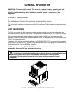
This Unit may be island-mounted or installed on a front or rear counter. Locate the Unit so the following
requirements are satisfied:
DANGER: To avoid possible fatal electrical shock or serious injury to the operator, it
is required that a GFCI (ground fault circuit interrupt) be installed in the electrical circuit
for the domestic Units. It is required that an ELCB (earth leakage circuit breaker) be
installed in the electrical circuit for the export Units
1. The Unit must be installed near a properly grounded electrical outlet with proper electrical require-
ments.The electrical circuit must be properly fused (slow-blow type fuse) or the circuit must be connected
through an equivalent HACR circuit breaker.The electrical outlet must be accessible for ease of connecting
and disconnecting the Unit power cord. No other electrical equipment should be connected to this circuit.
REFER TO UNIT NAMEPLATE FOR THE REQUIRED POWER CIRCUIT OPERATING VOLTAGE, HZ,
AND THE MINIMUM CIRCUIT AMPACITY OF THE UNIT. ALL ELECTRICAL WIRING MUST CONFORM
TO NATIONAL AND LOCAL ELECTRICAL CODES.
CAUTION: Do not place or store anything on top of the Unit.
2. A minimum of 15-inches clearance must be maintained above the Unit to the nearest obstruction (shelf,
cupboard, ceiling, etc.) and 6-inches clearance between back-side of the Unit and the wall. The front grille
of the Unit must be unobstructed to allow air to enter the hood.
3. Close to a permanent drain to route drip tray drain hose and water tank drain hose.
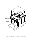
INSTALLING WATER ONLY LEVER KIT (P/N 3297) ON UF-1 DISPENSING
VALVE
The WATER ONLY LEVER KIT, UF-1 DISPENSING VALVE (item 10) is loose-shipped with all six-flavor
Dispensers equipped with UF-1 dispensing valves. Installation of this kit on the dispensing valve allows plain or
carbonated (depending on which dispensing valve the kit has been installed on) water only to be dispensed. If
desired, the kit may be installed at this time following instructions included with the kit.
INSTALLING UNIT
NOTE: Optional 4-inch Legs (P/N 314744000) that will elevate the Unit 4-inches above the countertop
are available. When ordering legs, order a quantity of four.
CUTTING HOLE IN COUNTERTOP
Place Unit in location on the countertop flush with the countertop edge. Mark Unit center line on edge of the
countertop, then move Unit off to one side. Starting at center line mark on edge of the countertop, measure
back 8-inches for location of the 2-1/2-inch diameter hole to be cut in the countertop. Cut a 2-1/2-inch hole in
the countertop where indicated. Place the Unit in position over the hole.
CONNECTING PLAIN WATER SOURCE LINE(S) TO UNIT
(see applicable Figure 2 or 3 and Figure 4)
NOTE: IMI Cornelius Inc. recommends that a water shutoff valve and water filter be installed in the
plain water inlet supply line (see applicable Figure 2 or 3) . A Cornelius Water Filter (P/N 313860000)
and Quick Disconnect Set (P/N 313867000) are recommended.