


13
312027000
1. Route syrup source lines from the syrup tanks location up to location under the countertop.
2. Route syrup source lines up through hole cut in the countertop to the barbed and labeled syrup inlet lines
on front of the Unit.
3. Connect the syrup source lines to the Unit barbed and labeled syrup inlet lines. Secure connections with
tubing clamps.
CONNECTING CO
2
SOURCE LINE TO UNIT
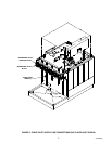
(see applicable Figure 2 or 3 and Figure 4)
1. Route CO
2
source line up to back side of the Unit.
2. Connect CO
2
source line to Unit labeled CO
2
inlet line. Seal connection with a tapered gasket.
SEALING UNIT BASE TO COUNTERTOP
1. To comply with NSF International (NSF) requirements within the United States, the Unit base must be
sealed to the countertop and all access holes to the Unit base must be completely sealed with a silastic
sealant such as Dow Corning RTV 731 or equivalent after completing installation of the Unit. Proceed as
follows to seal the Unit base to the countertop.
A. Tilt Unit up to expose bottom of the Unit base.
B. Connect a length of drain hose (not provided), long enough to reach a permanent drain, to drain fitting
on back side of the drip tray pan. Secure connection with DRAIN HOSE CLAMP (item 6).
C. Liberally apply silastic sealant such as Dow Corning RTV 731 or equivalent on the Unit base bottom
edges.
NOTE: Do not move Unit after positioning or seal from base to countertop will be broken.
D. Route drip tray drain hose down through hole in countertop, then lower Unit into operating position on
the countertop to complete seal from Unit base to the countertop.
E. Apply additional sealant around bottom of the base.The seal must have a minimum radius of 1/2-inch
to prevent crevices and to ensure a complete seal.
NOTE: Connection of drip tray drain hose to a permanent drain is recommended. Drip tray drain hose
routed to waste container is not recommended due to sanitation and cleaning problems.
F. Route lower end of drip tray drain hose to and connect to a permanent drain.
G. Install DRIP TRAY (item 1) in position on the Unit, then place CUP REST (item 2) in the drip tray.
PREPARING UNIT FOR OPERATION
FILL WATER TANK AND START REFRIGERATION SYSTEM
(see Figure 5)
1. Make sure plug in the water tank drain hose is secure.
NOTE: Use low-mineral-content water where a local water problem exists.
2. Remove plug from the drop-in refrigeration assembly platform water fill hole. Fill the water tank with clean
water until water runs out of the overflow groove on top front of the tank into the drip tray. USE LOW-MIN-
ERAL-CONTENT WATER WHERE A LOCAL WATER PROBLEM EXISTS. When the water tank is full, the
water level in the clear plastic water level tube should be approximately one inch from end of the tube.