


31202700017
OPERATOR’S INSTRUCTIONS
This section covers operating controls, daily pre-operation check, Unit operation, adjustments, replenishing
CO
2
and syrup supplies, cleaning and sanitizing, checking the drop-in refrigeration assembly condenser coil for
restrictions, checking the ice water bath, water pump yearly maintenance, and periodic cleaning of the CO
2
gas
check valves.
WARNING: Disconnect electrical power to the Unit to prevent personal injury before
attempting any internal maintenance. Only qualified personnel should service the internal
components or electrical wiring.
CAUTION: Do not place or store anything on top of the Unit.
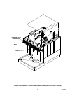
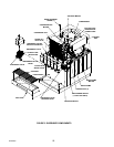
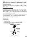
OPERATING CONTROLS
(see Figure 5)
DISPENSING VALVE LEVER
The dispensing valve lever, located on bottom of the valve, needs only to be pressed with cup or glass to dis-
pense product.
DISPENSING VALVE WITH WATER LEVER
The dispensing valve water lever will dispense only water when actuated.
DISPENSING VALVES KEYED LOCK-OUT SWITCH
The dispensing valves keyed lock-out switch, located on the left side of Unit (see Figure 5), must be in the “ON”
(vertical) position to operate the electric dispensing valves. The keyed lock-out switch in the “OFF” (horizontal)
position turns off electrical power to the dispensing valves only, but the refrigeration system will continue to
operate.
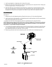
UNIT POWER SWITCH (115 VAC, 60 H
Z
UNITS ONLY)
The Unit power switch, located on the right side of the Unit (see Figure 5), must be in the “ON” position before
the Unit will operate.
CARBONATOR WATER PUMP MOTOR POWER SWITCH
The carbonator water pump motor power switch, located on the refrigeration assembly control box, (see Figure
5), must be in the “ON” position before the carbonator water pump motor will operate. The purpose of the power
switch is to turn off the carbonator water pump motor for service and maintenance. THE WATER SUPPLY TO
THE CARBONATOR WATER PUMP MUST BE TURNED ON BEFORE RESTARTING THE CARBONATOR.
STARVING THE WATER PUMP OF WATER WILL DAMAGE THE PUMP.
DAILY PRE-OPERATION CHECK
1. Check CO
2
cylinder regulator assembly 1800-psi gage and if the gage indicator is in the shaded (“change
CO
2
cylinder”) portion of the dial, the CO
2
cylinder is almost empty and must be replaced.