


312027000
23
NOTE: To readjust CO
2
regulator to a lower setting, loosen adjusting screw lock nut, then turn screw to
the left (counterclockwise) until pressure gage reads 5 psi lower than new setting will be. Turn the ad-
justing screw to the right (clockwise) until the gage registers new setting, then tighten the lock nut.
Adjusting Carbonator CO
2
Regulator.
Adjust primary CO
2
regulator (regulator controls Unit built-in cold carbonator CO
2
pressure) to a nominal 80
psig. Check for CO
2
leaks and repair if evident. INLET CO
2
PRESSURE TO CARBONATOR MUST NOT
EXCEED 125 PSIG.
Sugar Syrup Tanks Secondary CO
2
Regulator.
Adjust sugar syrup tanks secondary CO
2
regulator with 100 psi gage at 40 psig for syrup lines up to 10 feet in
length plus one pound for each additional length of 10 feet, plus one pound for each 2 feet of vertical lift. For
example; if syrup line total length is 30 feet and total vertical lift is 6 feet, then 40 psig + 2 psig (1-pound for ev-
ery 10 feet of length over 10 feet which is 20 feet) + 3 psig (1 pound for every 2 feet of vertical lift which is 6
feet); total equals 40 + 2 + 3 = 45 psig CO
2
regulator setting. Loosen lock nut on CO
2
regulator adjusting screw,
turn adjusting screw to the right (clockwise) until gage registers desired pressure, then tighten lock nut.
Low-Calorie (Diet) Syrup Tank Secondary CO
2
Regulator
Adjust low-calorie (diet) soft drink tank secondary CO
2
regulator with 30 psi gage to 10 psig for syrup lines up to
30 feet in length. Syrup lines longer than 30 feet in length may require a slightly higher CO
2
regulator setting of
12 psig maximum. Excessive CO
2
pressure may cause low-calorie syrup carbonation resulting in foam.
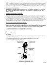
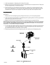
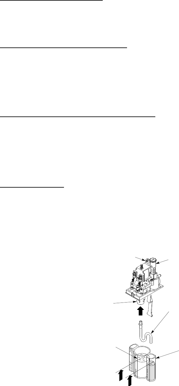
ADJUSTING DISPENSING VALVES WATER FLOW RATE
SF-1 Dispensing Valve.
(see Figure 6)
1. Remove acorn nut securing the dispensing valve cover, then remove the cover to expose the valve water
and the syrup flow controls.
2. Remove dispensing valve nozzle by turning nozzle counterclockwise and pulling down.
3. Remove syrup diffuser by pulling straight down.
ADJUSTABLE WATER
FLOW REGULATOR
ADJUSTABLE SYRUP
FLOW REGULATOR
NOZZLE
SYRUP DIVERSION
TUBE ASS’Y
(P/N 319540000)
WATER
CHAMBER
RATIO CUP
(P/N 311100000)
FIGURE 6. SF-1 DISPENSING VALVE