


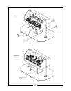
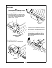
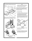
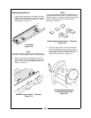
Now attach the drive coupler from the spin motor to the
reel. In most cases, town wobble extensions work well.
Figure 3-8
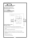
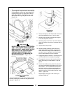
Be sure the extension is as straight as possible. Ad-
justing the spin motor on its bracket may be necessary.
Good alignment eliminates drive line chatter. Figure 3-
9
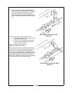
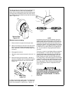
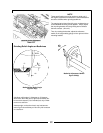
NOTE
The spin motor shaft must be removed and in-
stalled on the opposite side of the drive unit for
left drive reels. Do not turn drive assembly
around on work table bars. (Fig 3-9A)
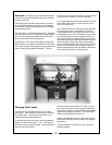
Once these steps have been completed, all mounting
brackets on the reel unit and bases should be se-
curely tightened. When grinding reels of the same
make and model, subsequent units will be easier to
place after the initial setup.
7. Close the rear canopy.
8. Open the front canopy.
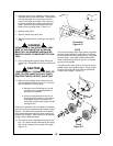
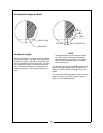
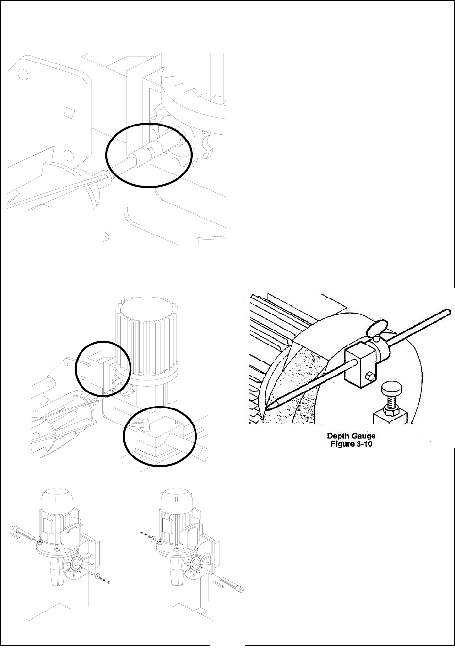
9. A depth gauge is supplied to check that the reel’s
center shaft is parallel with the wheel head travel.
Loosen the screw in the alignment stem collar
and slide the alignment stem for ward until it
makes contact with the reel’s center shaft.
Tighten the screw in the collar and remove depth
gauge. Move carriage to opposite end of the reel
and repeat instructions; taking notice of any dif-
ferences, make adjustments accordingly. Figure
3-10
10. After checking the alignment, remove the depth
gauge and close the front canopy.
11. Start the spin motor.
12. Adjust the dial on the RPM control to the proper
speed setting for the diameter of the reel being
ground. Refer to the chart located on the front
panel for the proper setting. Figure 3-11
15
Wobble Extensions
Figure 3-8
Spin Motor Brackets
Figure 3-9
Shaft Being Reversed
Figure 3-9 A