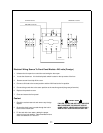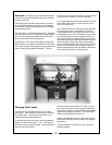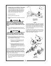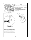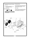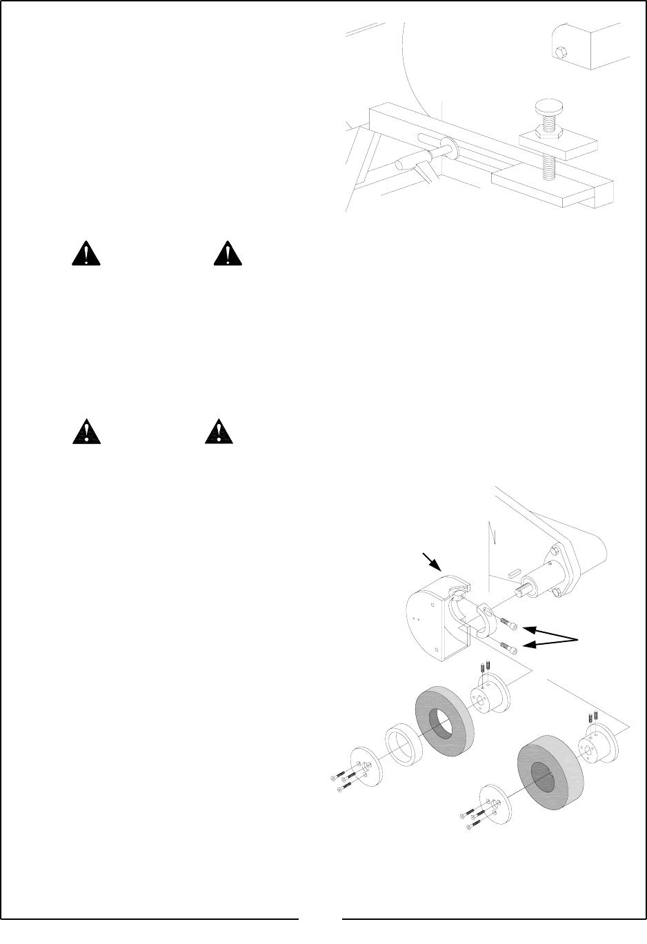
7. Starting at the end of a reel blade, carefully move
the wheel head in toward the blade. Take extreme
care that the blade you are grinding is placed
firmly on the finger guide slope. At this point, do
not let the grinding stone make contact with the
blade. Check for clearance between the “next
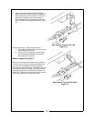
blade” and the grinding wheel. Figure 3-15
8. Start the wheel head.
9. Start eh coolant pump at full flow.
10. Adjust the wheel head “in” to achieve the desired
grind.
INITAILLY, UNTIL THE OPERATOR IS VERY
USED TO THIS OPERATION, WE RECOM-
MEND THAT HE GRINDING CARRIAGE BE
MOVED BY HAND TO INSURE BETTER CON-
TROL.
11. Pull the carriage along gently when starting the
relief grinds. Remember to have the coolant at full
flow.
WHEN MANUALLY TURNING THE REEL, BE
SURE TO KEEP HANDS CLEAR OF PINCH
POINTS BETWEEN THE REEL AND STONE.
12. Make sure the grinding wheel clears the end of
one blade before indexing to the next. There are
two (2) methods of relief grinding:
a. Manually move the carriage to one end
and return on the same blade before in-
dexing to the next blade.
b. As the carriage reaches the end of one
blade, the grinding wheel is moved clear
of the blade, the reel is indexed to the
next blade, and this blade if ground as the
carriage returns.
Continue this operation until every blade is completely
ground to the original equipment manufacturer’s speci-
fications. The thickness and hardness of the blades
being sharpened determines how much material can
be ground in one pass. With experience, the operator
will get a feel for different blades.
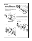
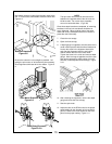
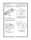
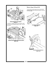
13. The angle of relief is adjustable using the thumb
bolt. Turn the thumb bolt clockwise for less angle
and counter-clockwise for a greater relief angle.
Figure 3-16
CAUTION
WARNING
NOTE
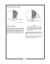
The lower the position of the finger guide, the greater
the relief angle imparted to each blade. Conversely,
the lower the center of the grinding wheel, the greater
the relief angle. If the blade is positioned from the
center of the grinding wheel (or above), no relief will
be ground on the blade.
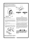
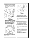
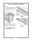
The guard (A) the finger guide is mounted to may be
rotated to gain more grinding angles. Simply loosen
the Allen screw (B) and move guard to the desired
location and re-tighten. Figure 3-17
18
Guard
Figure 3-17
A
B
Thumb Bolt
Figure 3-16


