


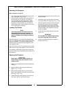
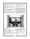
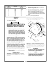
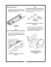
REEL
DIAMETER
REV/MIN DIAL
READING
4 375 10.00
5 300 7.70
6 250 6.25
7 215 5.40
8 190 4.75
9 170 4.30
10 150 3.80
RPM Setting
Figure 3-11
13. Start the wheel head.
PROLONGED CONTACT BETWEEN THE STONE
AND REEL MAY CAUSE THE STONE TO CHIP OR
BREAK APART, CAUSING SERIOUS INJURY TO
THE OPERATOR. DAMAGE TO THE REEL MAY
ALSO RESULT.
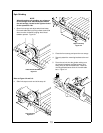
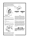
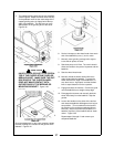
14. With the carriage in the center of the reel, care-
fully adjust wheel head “in” toward reel until slight
contact is made. Manually move grinding car-
riage left and right. If excessive vibrations or loud
grinding sounds occur, quickly adjust wheel head
“out,” away from the reel or press the “master kill”
button. Check mounting brackets, reel bearings,
etc., to make sure all are secure.
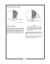
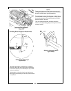
NOTE
Sometimes reels wear in either a concave or convex
fashion. If the grinding wheel makes contact with the
reel only in the center it indicates convex wear. Set
limit stops so wheel head travels just beyond points
of contact. Read through the following steps, then
grind reel until contact is make throughout wheel
head’s range of travel. Repeat step 15. If no contact
is made beyond points just ground, move limit stops
out slightly and regrind. Continue this procedure until
contact is make throughout entire length of reel. If
wear is concave, reel will have to be ground at each
end. Set limit stops as indicated by step 6 and grind
until contact is make throughout entire length of reel.
15. If the results of step 14 are satisfactory, engage
and start traverse.
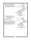
Engaging Traverse
5100 Series—Traverse engage lever is located on
the left side of the carriage plate. Move it to the cen-
ter position.
16. Start the coolant pump, using only a “trickle” of
coolant for spin grinding.
17. Begin the spin grinding operation. Grind the reel
until the leading edge has a square and sharp
edge. For best results, infeed the wheel at
0.001” (one tooth per stroke). See the following
instructions to set the auto infeed indexing ratchet
wheel.
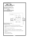
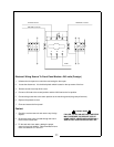
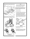
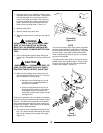
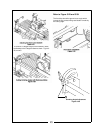
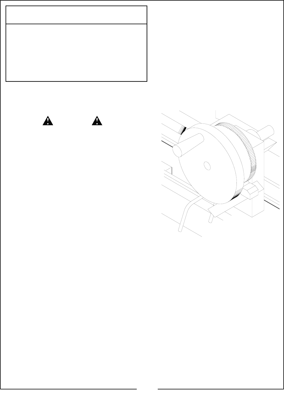
Indexing The Ratchet Wheel
The ratchet wheel, located just behind the hand
wheel, is used to automatically index the amount of
“in-feed” of the wheel head. Figure 3-12
The amount of “in-feed” per traverse cycle is set by
adjusting the screw on the center limit stop. One, two
or three teeth can be indexed, infeeding the grinding
wheel 0.001, 0.002 or 0.003 inch per traverse cycle
respectively.
IMPORTANT
For reels, only 0.001 inch per traverse cycle
is recommended by the manufacturer.
NOTE
The distance of travel will vary slightly with
the speed of travel. The carriage will
“overrun” the return stop if the speed is in-
creased without readjusting the screw.
CAUTION
16
Ratchet Wheel
Figure 3-12